반응형

Recently, a university undergraduate asked me on twitter for advice on becoming a graphics programmer within the games industry. I wrote a fairly detailed email response and thought the information was good enough to make an article for AltDevBlogADay. This is all my personal opinion of course.


최근에, 한 대학교 재학생이 나에게 트위터로 게임 산업에서 그래픽스 프로그래머가 되기 위한 조언을 구했다. 나는 꽤 상세하게 이메일 답장을 적었고 이 정보가 아티클로 만들기 충분하다고 생각했다. 이것은 물론 모두 나의 개인적인 의견이다.


If you're at university, you should research whether there's a programme to do a summer or year long internship at a games studio. There was nothing like that when I was at the University of Liverpool '97-'00 (or I wasn't aware of it), but I've seen people come through that kind of programme with much greater practical game development knowledge and it goes a long way towards persuading an employer to take you on. EA, Lionhead and other large companies tend to run this sort of programme so look on their job pages too. Beware that sometimes companies don't respond to intern applications for various reasons (team is deep in crunch, budget spent elsewhere, etc) and places are extremely limited.


만약 당신이 대학교에 재학중이라면, 게임 스튜디오에서 하계나 일년동안 할 수 있는 인턴쉽 프로그램이 있는지 조사해야한다. 내가 리버풀 대학교에 1997년 부터 2000년까지 다녔을때는 그런게 없었다. (혹은 내가 몰랐을 수도 있다.) 그러나 나는 훨씬 더 실용적인 게임 개발 지식을 가진 프로그램을 통해 온 사람들을 보았고 고용주에게 당신을 뽑도록 하게 끔 한다. EA Lionhead나 다른 대기업은 그들의 구인 페이지에 이런 종류의 프로그램을 볼 수 있도록 하는 경향이 있다. 몇몇 회사들은 다양한 이유로(팀이 크런치 모드에 들어갔다던가 예산이 다른곳에 낭비되었던가 등등) 인턴을 뽑지 않을 수 있으니 주의하라. 그리고 자리도 매우 제한적이다.


Your best bet is to make a graphics demo, either on your own or with a small group of people. You learn more by doing than by just reading. Pick a modern graphics technique that interests you and implement it. Even better, do more than one. This is also great training for motivating yourself to get a project finished which is often the hardest part of games development, for all disciplines. Make sure you're prepared to talk in detail about the choices you made, performance (in milliseconds, not frames per second!), quality, alternatives and trade offs in a job interview.


당신의 가장 좋은 베팅은 혼자서 혹은 사람들과 작은 그룹을 만들어 그래픽스 데모를 만드는 것이다. 당신은 단지 읽는 것 보다는 해보는 것에 의해 더 많이 배울 수 있다. 당신이 관심있는 최신 그래픽스 테크닉을 하나 고르고 구현해봐라. 물론 하나보다 더 많이 하면 더 좋다. 이것은 또한 게임 개발의 모든 분야에서 종종 가장 어려운 부분이라고 여겨지는 하나의 프로젝트를 완료했다는 것에 대해서 스스로에게 동기를 주는데 훌륭한 연습이 된다. 당신은 잡 인터뷰에서 만든 것, 퍼포먼스(밀리 세컨드 단위, fps아니고), 퀄리티, 대안, 트레이드오프에 대해 당신이 선택한 부분에 대해서 자세하게 말할 준비를 확실히 하라.
 

When I was in university I did a straight computer science course - there were barely any games courses available back then, but I still think that employers still value computer science graduates above games graduates as there's a perception that you learn a greater range of software engineering skills. This could be a misconception though, as games courses are a lot better than they used to be, but you may have to fight your corner in an interview and prove you know your stuff (and not just the curriculum you were taught).


내가 대학교에 다닐때, 나는 컴퓨터 사이언스 과목을 들었다. - 거의 어떠한 게임 관련 과목도 가능한 게 없었다. 하지만 나는 여전히 고용주들이 컴퓨터 사이언스 졸업생을 게임과 졸업생보다 더 넓은 범위의 소프트웨어 엔지니어링 스킬을 배웠다고 인식하고 있기 때문에 더 가치있게 본다고 생각한다. 이것은 게임 과목들이 예전보다 많이 좋아졌기 때문에 오해일 수 있지만 면접을 볼때 맞써 싸워야 하는 부분이고 당신이 알고있는 것들을 증명해야만 한다. (당신이 배웠던 커리큘럼 뿐만 아니라)
 
Computer science courses also tend to be quite maths heavy (I would hope games courses are similar), which is vital for graphics programming. Make sure you understand homogeneous coordinates, matrix maths, dot products, cross products, quaternions, normal vectors, tangent bases, etc and how these things (and countless others) are useful for transforming and lighting geometry. Learn big O notation for algorithmic execution time, understand colour spaces, gamma correction, what high dynamic range means and so on. Learn some basic lighting models - Lambert, Phong, Blinn, etc.

컴퓨터 사이언스 과목은 또한 그래픽스 프로그래밍에 필수인 꽤 깊은 수준의 수학을 배우는 경향이 있다. (나는 게임 과목도 비슷할 거라고 희망한다.) 동차 좌표계, 행렬  수학, 내적, 외적, 쿼터니언, 노말 벡터, 탄젠트 기저 등등을 확실히 이해하고 있어야 하고 이것들(셀수 없이 많은 다른 것들도)이 어떻게 변환과 조명, 기하에 유용한지를 이해해야 한다. 알고리즘의 실행 시간을 위해 빅-O 표기법을 배우고 색상 공간, 감마 보정, HDR의 무슨 의미인가 등등을 배워야 한다. 몇가지 기본적인 조명 모델을 배워야 한다. - 램버트, 퐁, 블린 등등.


Software

In my experience, Visual Studio is pretty much universal as a code IDE (except for Apple, Linux, Android and Nintendo games), though you can of course use your favourite editor if you really want to, as long as you know Visual Studio. There is a free Express edition available from Microsoft (http://www.microsoft.com/express/Windows/), so it won't cost you any money to learn. The PS3 is a little different as there is a separate hardware specific debugger, but you should be able to learn that on the job.

소프트웨어
물론 당신이 정말 원한다면 당신이 가장 좋아하는 에디터를 사용할 수 있지만, 내 경험으로는 Visual Studio가 꽤 많이 세계적으로 사용되는 코드 IDE이기 때문에 (애플, 리눅스, 안드로이드, 닌텐도 게임을 제외하고) 적어도 Visual Studio는 알아두자. Microsoft에서 Express 버전은 무료로 사용가능하며 배우는데 어떠한 돈도 지불하지 않는다. PS3는 별도의 하드웨어 종속적인 디버거가 있어 조금 다르지만 직장에서 그것을 배울 수 있어야 한다.
 
You should be familiar with a source control system. Perforce (www.perforce.com) is a good choice as a lot of game studios use it and it's free for single users. Try to learn it on a project with other people as merging, branching and integration are good skills to have. With all source control systems, similar concepts apply so it's essential knowledge to have. Shockingly, my university course never mentioned source control and I was naive enough to believe that people just shared code over the network or on floppy disks.
 
당신은 소스 컨트롤 시스템에도 친숙해야만 한다. 퍼포스가 많은 게임 스튜디오에서 사용하기 때문에 하나의 좋은 선택이될 수 있고 개인 사용자에게 무료다. 머징, 브랜칭, 인티그레이션은 알아둬야 할 좋은 기술이므로 다른사람들과 함께 하나의 프로젝트를 통해 배우도록 노력해라. 모든 소스 컨트롤 시스템에는 유사한 컨셉이 적용되기 때문에 필수적인 지식이다. 놀랍게도 나의 대학 강의에서는 소스 컨트롤에 대해 전혀 언급하지 않았고 나는 사람들이 단지 네트워상으로나 플로피 디스크로 코드를 공유한다고 믿었었다.

As you're unlikely to have access to devkits at home or in university, you'll most likely be learning your skills on PC. In what may come as a surprise from someone with a decade's game development experience, I don't know much OpenGL as there's never been a pressing need for me to learn it. Most PC games use DirectX, though if you learn DirectX 11, make sure you also learn DirectX 9 as it's still current for Xbox 360 and many PC games still use it to support the dwindling, but still large Windows XP market. DirectX 10 is completely superseded by DirectX 11, so it is not worth learning (you can write DirectX 11 games for DirectX 10 hardware, and even DirectX 9 hardware).

집이나 학교에서는 개발킷에 접근할 수 없기 때문에 PC에서의 기술을 배워게 될 것이다. 십년간 게임 개발 경험을 가진 사람에게 놀라움으로 다가올만한게 나는 OpenGL을 배워야만 할 필요가 없었기 때문에 잘 모른다. 대부분의 PC게임은 DirectX를 사용하고 만약 DirectX 11을 배웠더라도 Xbox 360과 줄어들고는 있지만 윈도우 XP 시장이 여전히 크기 때문에 많은 PC 게임들이 여전히 DirectX9을 사용하고 있어서 배워야 한다. (하지만 번역중인 현재는 Window 10이 나왔기 때문에 DirectX 11로 봐도 될 듯 하다!) DirectX 10은 완전히 DirectX 11에 의해 대체되었기 때문에 배울 필요는 없다. (DirectX 10 하드웨어, 심지어 DirectX 9 하드웨어에서 돌리는 게임을 DirectX 11로 작성할 수 있다.)
 
It's also definitely worth learning a graphical debugger. PIX for Windows isn't as good as the Xbox 360 version, but there are fantastic free alternatives (Intel GPA - http://software.intel.com/en-us/articles/intel-gpa/, Nvidia Parallel Nsight - http://developer.nvidia.com/nvidia-parallel-nsight). These tools are not just for performance tuning on the GPU - they're also for debugging your draw calls, working out why something doesn't draw, why it looks wrong, and so on. You can also learn about how a GPU works as you can see all the renderstates, shaders, meshes, textures, etc for any draw call in a frame and really understand what the GPU is actually doing with the data you give it.

또한 그래픽 관련 디버거는 배울 가치가 있다. PIX for Windows는 Xbox 360 버전만큼 좋지 않지만 멋진 무료 대체 프로그램들이 있다. (Intel GPA, Nvidia Parallel Nsight) 이 툴들은 GPU상에 퍼포먼스 튜닝을 위한 것 뿐만 아니라 드로우콜, 왜 어떤것이 안 그려지는가, 왜 이상하게 보이는가 등등을 디버깅할 수 있다. 한 프레임 안의 어떠한 드로우 콜에 대해서 렌더 스테이트, 쉐이더, 메쉬, 텍스쳐등 모든것을 볼 수 있기 때문에 GPU가 어떻게 동작하는지에 대해서 배울수 있고 GPU가 당신이 보낸 데이터를 가지고 실제로 어떤 일을 하는지에 대해서 이해할 수 있게 된다.
 
Other Duties
As a graphics coder you'll probably have to do some tools work too, working with mesh compilers, animation compilers, plugins for Maya/3DS Max or in-house editors for the artists to use. Remember that your job is to provide technology to support the artists in their daily work, so it needs to be presented in a friendly manner. If you give your art team a tool that lets them tweak some coefficients of a fancy rendering algorithm and they have no idea what the numbers mean, they probably won't use it. Also, technical artists are your friends - they're the best people to talk about requirements for artists and to work out the best workflow for the content creators.

다른 의무들
그래픽스 개발자로서 당신은 또한 메쉬 컴파일러, 애니메이션 컴파일러, Maya/3DS Max 플러그인이나 아티스트가 사용하는 인 하우스 에디터와 같은 몇개의 툴들을 다룰 수 있어야 한다. 당신의 일은 아티스트들이 일상 업무를 지원해주기 위한 기술을 제공하는 것임을 기억하고 그들에게 친숙한 방식을 제공해야 할 필요가 있다. 만약 당신의 아트 팀에게 환상적인 렌더링 알고리즘을 위한 몇개의 계수 값을 바꾸기 위해서 하나의 툴을 제공한다면 그들은 그 숫자들이 의미하는 것에 대해 알지 못할 것이고 아마도 사용하지 못할 것이다. 물론 테크니컬 아티스트들은 여러분의 동료이다. - 그들은 아티스트들의 요구사항에 대해서 이야기할 수 있는 가장 좋은 사람이고 컨텐츠 생성을 위한 가장 좋은 워크플로우를 찾아낸다.

It's also good to learn general performance and optimisation techniques as this often falls to the graphics/engine team to do. You probably won't have to write any (or very little) raw assembler, but you ought to be familiar with what the C/C++ compiler is doing to your code, how to spot problems and what to do about them. For example, one of the biggest performance problem will be L2 cache misses (you lose hundreds of cycles per miss on all modern hardware), so learn techniques to reduce them (almost always changing the data, not the code is the fix).

또한 그래픽스/엔진 팀이 해야하는 일반적인 퍼포먼스, 최적화 기법을 배우면 좋다. 당신은 아마도 거의(혹은 매우 적게) 어셈블리어를 작성해야만 하지는 않을 것이지만 C/C++ 컴파일러가 당신의 코드를 어떻게 하는지, 어떻게 문제점을 발견하고 그것들에 대해서 무엇을 하는지에 대해서는 친숙할 필요가 있다. 예를들어 가장 큰 퍼포먼스 문제중 하나는 L2 캐쉬 미스 문제일 것이다. (모든 현대 하드웨어에서 미스당 수백 사이클을 잃어버린다.) 그것들을 줄이기 위한 기술을 배운다. (거의 항상 코드가 아닌 데이터를 변경하는 것으로 해결한다.)


Online Learning Resources

Online resources are a goldmine, and there's much better stuff out there than there was when I was at university as a lot of companies publish papers on their techniques which are pretty useful stuff. A few examples...

http://www.valvesoftware.com/company/publications.html

http://publications.dice.se/

Also there are a few good blogs posting regularly about graphics. A few good examples...

http://aras-p.info/blog/ - Lost in the Triangles. Aras Pranckevičius's blog (a lead programmer for Unity).

http://www.realtimerendering.com/blog/ - Real Time Rendering has good information (also the book is a worthwhile read!)

http://www.humus.name/ - Another good graphics programming blog.

온라인 강좌
온라인 리소스는 금광과 같고 내가 대학교에 다닐때 보다 훨씬 더 좋은 것들이 많다. 많은 회사들이 자신들의 기술에 대해서 매우 유용한 자료들을 공개하고 있다. 예를들어 위 링크와 같다.
또한 그래픽스에 대해 규칙적으로 포스팅 하는 좋은 블로그들이 몇개 있다.
위에 링크 참조!
 

Make sure you read the relevant presentations from GDC (very useful) and SIGGRAPH (slightly less useful as a lot of it is for non-realtime graphics, but useful as a crystal ball for future techniques).

My last handy tip is that if you live near a big dev studio, find out which pub they go drinking at after work and join in on a Friday night. You'll learn a lot just chatting with developers. You can also join twitter and talk to many games developers there who are willing to share their experience.


GDC(매우 유용한)와 SIGGRAPH (리얼타임이 아닌 그래픽스에 대해 더 많이 유용해서 약간 덜 유용하지만 미래의 기술들에 대해 수정구슬(?)과 같이 유용한) 관련있는 발표를 읽어라. 나의 마지막 유용한 팁은 만약 당신이 큰 개발 스튜디오 근처에 산다면 그들이 업무가 끝나고 술 마시러 가는 펍을 찾고 금요일 밤에 가라. 당신은 개발자과 많은 이야기를 나누며 배울 수 있을 것이다. 또한 트위터에 가입하고 그들의 경험을 기꺼이 공유해줄 많은 게임 개발자들과 이야기를 나누어라.


출처: <http://www.altdev.co/2011/05/10/so-you-want-to-be-a-graphics-programmer/>

반응형
Posted by msparkms
,
반응형


    출처: <http://gamasutra.com/blogs/OliverFranzke/20140718/221347/How_to_become_a_Graphics_Programmer_in_the_games_industry.php>


    As we were recently hiring a new Graphics Programmer at work I had to identify what kind of technical knowledge and skills we would expect from a potential candidate. Although this definition will be somewhat specific to what we look for in a candidate, it might still be of interest to other coders trying to score a job in the industry as a Rendering Engineer.
     

    최근에 새로운 그래픽스 프로그래머를 고용할 우리가 잠재적인 후보자로 부터 기대하는 기술적인 지식과 스킬을 가지고 있는가를 확인해야만 했다.  비록 정의가 한명의 후보자에게서 우리가 찾고자 하는 특정의 어떤것이기는 하지만 렌더링 엔지니어로써 산업에서 하나의 직업으로 점수를 얻고자 하는 다른 코더들에게도 흥미로울 이다.
     

    This post might help you to identify areas to learn about in order to get you closer to your goal of becoming a Graphics Engineer, whether you just finished your degree or perhaps have been working in the games industry in a different role. Alternately, if you are a seasoned Rendering Programmer, then you know all of this stuff and I would love to hear your comments on the topic.
     

    포스트는 당신이 학위를 마쳤든 아니면 다른 직업 군으로 게임 산업에서 일을 하고 있는 중이든 그래픽스 엔지니어가 되려는 당신의 목표에 가까워 지기 위해서 배워야 하는 영역을 배우는데 도움을 것이다.  반대로, 만약 당신이 숙련된 렌더링 프로그래머라면 당신은 내용의 모든 부분을 것이고 주제에 대해서 당신의 코멘트를 듣고 싶다.


    Know the Hardware
     

    Learning about the strengths and weaknesses of the hardware that will execute your code should be important for any programmer, but it's an essential skill for a Graphics Engineer. Making your game look beautiful is important; getting all of the fancy effects to run at target frame rate is often the trickier part.


    당신의 코드가 실행되는 하드웨어의 장점과 단점에 대해서 배우는 것은 어떤 프로그래머에게도 중요하지만 그래픽스 엔지니어에게는 필수적인 스킬이다. 당신의 게임을 아름답게 보이도록 만드는 것은 중요하다.  환상적인 이펙트들을 타겟 프레임 레이트에 모두 실행시키는 것은 보통 트릭키한 부분이다.


    Of course, it would be unrealistic to expect you to know every little detail about the underlying hardware (especially if you are just starting out) but having a good high-level understanding of what is involved to make a 3D model appear on screen is a mandatory skill, in my opinion. A candidate should definitely know about the common GPU pipeline stages (e.g. vertex- and pixel-shader, rasterizer, etc.), what their functionality is and whether or not they are programmable, configurable or fixed.


    물론 하드웨어 기초를 이루는 부분에 대해 모든 작은 디테일까지 당신이 안다고 기대하는것(특히 만약 당신이 이제 시작한 사람이라면) 비현실적이지만, 생각으로는 화면에 하나의 3D 모델이 표시되는데 연관된 것들에 대해 훌륭한 고수준의 이해는 필요한 스킬이다. 후보자들은 공통의 GPU 파이프라인 스테이지(예를 들어 버텍스, 픽셀 쉐이더, 레스터라이져 등등) 대해서 그것들의 기능이 무엇이고 프로그래밍 가능한지, 설정이 가능한지, 고정된건지를 분명하게 알아야만 한다.


    Very often, there are many ways to implement a rendering effect, so it’s important to know which solution will work best on a given target device. Nothing is worse than having to tell the artists that they will have to modify all of the existing assets, because the GPU doesn’t support a necessary feature very well.


    때때로, 렌더링 이팩트를 구현하는 방법은 많이 있어서 주어진 타겟 디바이스에서 가장 동작하는 솔루션이 무엇인지 아는 것이 중요하다. 아티스트들에게 GPU 필요한 기능을 지원해주지 않기 때문에 존재하는 어셋들의 모두를 수정해야만 한다 라고 말해야 하는 보다 최악인 것은 없다.


    For example, the game that I am currently working on is targeting desktop computers as well as mobile devices, which is important because mobile GPUs have very different performance characteristics compared to their desktop counterparts (check out my 5 minute micro talk on this topic if you are interested). Our team took this difference into account when making decisions about the scene complexity and what kind of effects we would be able to draw.


    예를 들어, 내가 현재 작업중인 게임은 데스크탑 컴퓨터 타겟으로 하고 있고 또한 모바일 디바이스를 타겟으로 하고 있다. 모바일 디바이스는 데스크탑에 있는 부분과 비교하여 매우 다른 퍼포먼스 특성을 가지고 있는 모바일 GPU 때문에 중요. (만약 관심이 있다면 토픽에 대해서 나의 5 마이크로 토크를 확인해봐라) 우리 팀은 씬의 복잡도와 우리가 그릴 있는 이펙트들의 종류를 결정할 차이점을 고려했다.


    A great way to learn more about GPUs is to read chapter 18 of Real-Time Rendering (Third Edition), because it contains an excellent overview of the Xbox 360, Playstation 3 and Mali (mobile) rendering architectures.


    GPU 대해서 많은 것을 배우는 좋은 방법은 Real-Time Rendering (3rd) 18번째 챕터를 읽는 것이다. 왜냐하면 여기에 Xbox 360, PS3, Mali (모바일) 렌더링 아키텍쳐의 훌륭한 오버뷰를 포함하고 있기 때문이다.


    Good Math Skills


    Extensive knowledge of trigonometry, linear algebra and even calculus is very important for a Graphics Programmer, since a lot of the day to day work involves dealing with math problems of varying complexities.


    나날이 가지각색의 복잡한 수학적 문제들을 다루는 것을 포함한 업무를 하기 때문에 삼각법, 선형대수학, 심지어 미적분의 해박한 지식은 그래픽스 프로그래머에게 매우 중요하다.


    I certainly expect a candidate to know about the dot and cross products and why they are very useful in computer graphics. In addition to that, it is essential to have an intuitive understanding for the contents of a matrix, because debugging a rendering problem can make it necessary to manually ‘decompose’ a matrix in order to identify incorrect values. For example, not that long ago I had to fix a problem in our animation system and was able to identify the source of the problem purely by looking at the joint matrices.


    나는 내적과 외적에 대해 알고 그것들이 컴퓨터 그래픽스에서 매우 유용한지를 아는 후보자를 기대한다. 추가적으로 행렬 개념에 대해 직관적인 이해를 가진 것은 필수다. 왜냐하면 렌더링 문제의 디버깅은 올바르지 않은 값을 식별하기 위해서 행렬을 수동적으로 분해하는 것을 필요로 할 수 있기 때문이다. 예를 들어, 얼마전에 우리 애니메이션 시스템의 문제를 해결해야만 했고 조인트 행렬을 살펴 보는 것으로 문제의 근원을 찾을 있었다.


    In my opinion, a candidate should be able to analytically calculate the intersection between a ray and a plane. Also, given an incident vector and a normal, I would expect every Rendering Engineer to be able to easily derive the reflected vector.


    생각에는 후보자는 광선과 평면 사이의 충돌을 분석적으로 계산할 있어야만 한다. 또한 입사 벡터와 노말이 주어졌을 , 나는 모든 렌더링 엔지니어들이 쉽게 반사 벡터를 구할 있다고 기대한다.


    There are plenty of resources available on the web. You can find some good resources here. The book "3D Math Primer for Graphics and Game Development" does a great job explaining a lot of the fundamentals like vectors, matrices and quaternions to name just a few topics. I would also strongly recommend attempting to solve some of these problems on a piece of paper instead of looking at a preexisting solution. It’s actually kind of fun, so you should definitely give it a try.


    웹상에 유용한 리소스들이 많이 있다. 당신은 여기서 몇몇개의 좋은 리소스들을 찾을 있을 것이다. 3D Math Primer for Graphics and Game Development 책은 몇가지 예를 들어 벡터, 행렬, 쿼터니언과 같은 많은 기초들에 대해 멋지게 설명해준다. 나는 또한 기존의 해답을 보는 대신에 종이에 문제들 일부를 풀어보기를 강력하게 추천한다. 이것은 실제로 재밌기도 하고 분명히 한번 해봐야 한다.


    Passion for Computer Graphics


    An ideal candidate will keep up to date with the latest developments in computer graphics especially since the field is constantly and rapidly advancing (just compare the visual fidelity of games made 10 years ago with what is possible today).


    이상적인 후보자는 특히 끊임없이 빠르게 발전하는 분야이기 때문에 최신의 컴퓨터 그래픽스 개발에 대해 최신 트렌드를 유지할 것이다. (단지 10년전 게임과 오늘날 있는 것들의 비주얼적인 정확함을 비교해보라.)


    There are plenty of fascinating research papers (e.g. current SIGGRAPH publications), developer talks (e.g. GDC presentations) and technical blogs available on the internet, so it should be pretty easy to find something that interests you. Make sure to check out the blogs of fellow Rendering Engineers for some really inspiring articles!


    매혹적인 논문들(예를 들어 최근 씨그래프에서 발행) 개발자들의 발표(예를 들어 GDC 발표) 그리고 인터넷 상에 유용한 기술적 블로그들이 많이 있다. 당신이 관심있어 하는 어떤 것이든 쉽게 찾을 있다. 몇몇개의 정말 감명 깊은 아티클들을 위해 렌더링 엔지니어 동료들의 블로그들을 확인해 봐라.


    Of course implementing an algorithm is the best way to learn about it, plus it gives you something to talk about in an interview. Writing a cool graphics demo also helps you to practice your skills and most of all it is a lot of fun.


    물론 알고리즘을 구현하는것은 그것을 배우는 가장 좋은 방법이다. 추가로 면접때 이것에 대해 말할거리도 준다. 멋진 그래픽스 데모를 작성하는 것은 또한 당신의 스킬을 연습하는데 도움을 주고 무엇보다도 재밌다.


    If you want to maximize your chances of getting a job make sure to spend some time making your demo look pretty. You may have implemented the most efficient tessellation algorithm, but if people can't see what's going on they might not be as impressed as they should be. Creating visually pleasing images is a big part of the profession, so it's generally a good idea to show that you have this skill as well.


    만약 취직의 기회를 최대로 높이길 원한다면 당신의 데모가 예뻐 보이도록 만드는데 시간을 사용해야만 한다. 당신이 가장 효과적인 테셀레이션 알고리즘을 구현했지만 만약 사람들이 무슨 일인지 알지 못한다면 감명을 받았어야 만큼 받지 못할 것이다. 시각적으로 만족을 주는 이미지를 만드는 것은 프로의 부분이고 또한 일반적으로 당신이 가진 스킬을 보여주는 좋은 아이디어다.


    Performance Analysis and Optimization


    One of the responsibilities of a Graphics Programmer is to profile the game in order to identify and remove rendering related bottlenecks. If you are just starting out I wouldn’t necessarily expect you to have a lot of practical experience in this area, but you should definitely know the difference between being CPU and GPU bound.


    그래픽스 프로그래머의 책임중 하나는 렌더링과 관련된 보틀넥을 찾고 없애기 위해서 게임을 프로파일링 하는 것이다. 만약 당신이 시작하는 사람이라면 당신이 분야에서 많은 실용적인 경험을 가지는게 필수라고 기대하지는 않는다. 하지만 CPU GPU 바운드 사이의 차이점을 분명하게 알아야만 한다.


    An ideal candidate will have used at least one graphics analysis tool like PIX (part of the DirectX SDK), gDEBugger or Intel’s GPA. These applications are available for free allowing you to take a closer look at what’s going on inside of a GPU, isolate bugs (e.g. incorrect render-state when drawing geometry) and identify performance problems (e.g. texture stalls, slow shaders, etc.)


    이상적인 후보자는 적어도 하나의 PIX(DirectX SDK 포함되어 있음),  gDEBugger, Intel's GPA 같은 그래픽스 분석 툴을 사용할 있을 것이다. 어플리케이션들은 무료로 GPU 내부가 어떻게 동작하는지 가까이 있도록 해주고 버그들을 격리 시키고 (예를들어 지오메트리를 그릴 잘못된 렌더 스테이트) 퍼포먼스 문제(텍스쳐 스톨, 느린 쉐이더 등등) 식별할 있게 해준다.


    Conclusion


    The job of a Graphics Programmer is pretty awesome since you’ll be directly involved with the visual appearance of a product. The look of a game is very often the first thing a player will know about it (e.g. trailers, screenshots) which has been very gratifying for me personally.


    그래픽스 프로그래머의 잡은 제품의 시각적 외향에 직접적으로 참여하게 되면 멋지다.  게임의 외형은 때때로 플레이어에게 개인적으로 나에게 매우 기쁨을 준다는 것에 대해 처음으로 알게 해준다. (예를들어 트레일러나 스크린샷)


    Truth be told, you won’t be able to write fancy shaders every day. You should be prepared to work on other tasks such as: data compression (e.g. textures, meshes, animations), mathematical and geometry problems (e.g. culling, intersection computations) as well as plenty of profiling and optimizations. Especially, the latter task can be very challenging since the GPU and the associated driver cannot be modified.


    사실대로 말하자면 당신은 매일 환상적인 쉐이더를 작성할 수는 없다. 당신은 데이터 압축 (예를들어 텍스쳐, 메쉬, 애니메이션), 수학적이고 기하학적인 문제들(컬링, 충돌 계산), 또한 많은 프로파일링과 최적화와 같은 다른 작업들도 준비가 되어 있어야만 한다. 특히 후자의 일이 GPU 관련된 드라이버들은 수정할 없기 때문에 매우 도전적일 있다.


    To sum up, becoming Rendering Engineer requires a lot of expert knowledge, and it is certainly not the easiest way to get a foot in the proverbial games industry door, but if you are passionate about computer graphics it might be the right place for you!


    요약하자면 렌더링 엔지니어가 되는 것은 많은 전문적인 지식이 필요하고 유명한 게임업계의 문안에 발을 들이는 가장 쉬운 방법은 분명하게 없다. 하지만 만약 당신이 컴퓨터 그래픽스에 대해 갈망을 가지고 있다면 그것이 당신을 올바른 위치에 있게 것이다.


    The Beginner's Checklist


반응형
Posted by msparkms
,
반응형

원본 :  http://content.gpwiki.org/index.php/D3DBook:Screen_Space_Ambient_Occlusion 

Screen Space Ambient Occlusion

Introduction

There are many ways in which to increase the realism of a computer generated image. One such method is to calculate the effects of shadowing on an object when evaluating its lighting equations. There is a very wide variety of shadowing techniques available for use in real-time computer graphics, with each technique exhibiting both advantages and disadvantages. In general, shadowing techniques try to strike some balance between shadow quality and runtime performance.

One such technique has been termed Screen Space Ambient Occlusion (SSAO). This technique was originally discussed by Martin Mittring when presenting the paper “Finding Next Gen” at the 2007 SIGGRAPH conference. The basic concept behind the algorithm is to modify the ambient lighting term [see the lighting section of the book for details about the lighting equation :Foundation and theory] based on how occluded a particular point in a scene is. This was not the first technique to utilize the concept of ambient occlusion, but as you will see later in this chapter Screen Space Ambient Occlusion makes some clever assumptions and simplifications to give very convincing results while maintaining a high level of performance.

컴퓨터에서 생성되는 이미지의 현실성을 높이기 위한 많은 방법들이 있다. 이러한 방법중 하나는 조명 방정식을 평가할 때 오브젝트에 그림자 효과를 계산하는 것이다. 실시간 컴퓨터 그래픽스에서 사용할 수 있는 매우 널리 알려진 다양한 그림자 기법들이 있다. 각각의 기법들은 장단점을 가지고 있다. 보통 그림자 기법들은 그림자 퀄리티와 실시간 퍼포먼스 사이에서 약간의 밸런스를 취한다.

이러한 테크닉중 하나는 SSAO라고 한다. 이 기법은 2007 SIGGRAPH 컨퍼런스에서 "Finding Next Gen" 발표때 Martin Mittring에 의해 처음으로 논의되었다. 이 알고리즘의 기본 개념의 배경은 씬에서 특정 점이 얼마나 차폐되었는지를 기반으로 환경광을 수정하는 것이다. [Foundation and Theory에 조명 방정식에 대해서 자세하게 알고 싶으면 책의 조명 부분을 봐라.] 이것은 Ambient Occlusion의 개념을 이용하는 첫번째 테크닉은 아니지만, 이 챕터 나중에 SSAO가 매우 확실한 결과를 주는 반면에 높은 레벨의 퍼포먼스를 내기 위해 얼마나 영리한 가정과 단순화를 했는지 알게 될 것이다.

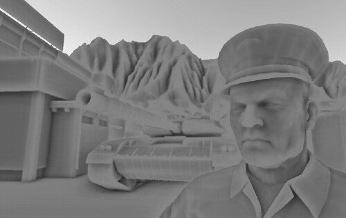
Figure 1 SSAO Screen Shot.png
Figure 1: Sample rendering utilizing screen space ambient occlusion.

In this chapter, we will explore the theory behind the Screen Space Ambient Occlusion technique, provide an implementation of the technique that utilizes the Direct3D 10 pipeline, and discuss what parameters in the implementation can be used to provide scalable performance and quality. Finally, we will discuss an interactive demo which uses the given implementation and use it to give some indication of the performance of the algorithm.

이 챕터에서 우리는 Direct3D 10 파이프라인을 사용하는 구현을 제공하여 SSAO 기법의 뒤에 깔린 이론을 알아볼 것이고 구현에서 어떤 인자들이 재볼 수 있는 퍼포먼스와 퀄리티를 제공하는데 사용되는지 의논할 것이다. 마지막으로 우리는 주어진 구현을 사용하는 데모에 대해 의논하고 알고리즘의 퍼포먼스의 징후를 보는데 사용할 것이다.

Algorithm Theory

Now that we have a background on where screen space ambient occlusion has come from, we can begin to explore the technique in more detail. SSAO differs from its predecessors by making one major simplification: it uses only a depth buffer to determine the amount of occlusion at any given point in the current scene view instead of using the scene information before it is rasterized. This is accomplished by either directly using the depth buffer or creating a special render target to render the depth information into. The depth information immediately surrounding a given point is then scrutinized and used to calculate how occluded that point is. The occlusion factor is then used to modify the amount of ambient light applied to that point.

The generation of an occlusion factor using the SSAO algorithm is logically a two step process. First we must generate a depth texture representation of the current view of the scene, and then use the depth texture to determine the level of occlusion for each pixel in the final view of the current scene. This process is shown below in Figure 2.

이제 우리는 SSAO가 어디로 부터 왔는지 그 배경을 알게되었다. 이제 더 자세히 이 기법에 대해 탐험을 시작해 볼 수 있다. SSAO는 주요한 단순화를 함으로써 전에 있던 것들과는 다르다. : 이 기법은 레스터라이징 전에 화면 정보를 사용하는 대신에 현재 씬 뷰에 주어진 점에서 차폐된 정도를 계산하기 위해 오직 깊이버퍼만 사용한다. 이것은 직접적으로 사용하는 깊이 버퍼나 깊이 정보를 렌더링하기 위한 특정 렌더타겟의 생성에 의해서 수행된다. 주어진 한 점의 주변을 감싸는 깊이 정보는 조사되고 그 점이 얼마나 차폐되었는지 계산하는데 사용된다. 차폐 요소는 그점에 적용되는 환경 광의 양을 수정하는데 사용되어진다.

SSAO 알고리즘에 사용되는 차폐 요소의 발생은 논리적으로 두 스텝으로 진행된다. 먼저 우리는 현재 씬의 뷰의 화면을 렌더링하는 깊이 텍스쳐를 생성해야만 하고, 그리고 나서 현재 씬의 마지막 뷰에 각각의 픽셀에 차폐정도를 결정하기 위해 깊이 텍스쳐를 사용한다. 이 과정은 뒤의 Figure 2를 보자.


Figure 2 SSAO Algorithm.png
Figure 2: Overview of the screen space ambient occlusion technique.

The simplification of using only a depth buffer has several effects with respect to performance and quality. Since the scene information is rasterized into a render target, the information used to represent the scene is reduced from three dimensional to two dimensional. The data reduction is performed with the standard GPU pipeline hardware which allows for a very efficient operation. In addition to reducing the scene by an entire dimension, we are also limiting the 2D scene representation to the visible portions of the scene as well which eliminates any unnecessary processing on objects that will not be seen in this frame.

The data reduction provides a significant performance gain when calculating the occlusion factor, but at the same time removes information from our calculation. This means that the occlusion factor that is calculated may not be an exactly correct factor, but as you will see later in this chapter the ambient lighting term can be an approximation and still add a great deal of realism to the scene.

Once we have the scene depth information in a texture, we must determine how occluded each point is based on it's immediate neighborhood of depth values. This calculation is actually quite similar to other ambient occlusion techniques. Consider the depth buffer location shown in Figure 3:

오직 하나의 깊이 버퍼를 사용하는 단순화는 퍼포먼스와 퀄리티 면에서 여러모로 효과적이다. 씬 정보를 렌더 타겟에 레스터라이징한 이후로, 씬을 표현하기 위해 사용되는 정보는 3차원에서 2차원으로 줄어든다. 이 데이터 축소는 매우 효과적인 연산을 가능하게 하는 표준 GPU 파이프라인 하드웨어로 행해진다. 전체 씬의 차원이 감소한 것 뿐만아니라 추가로 2D 씬의 표현을 씬의 보여진 부분만으로 제한함으로써 이번 프레임에 보이지 않을 오브젝트에 대해 어느 불필요한 처리를 제거할 수 있다. 

데이터 축소는 차폐 요소를 계산할 때 분명한 퍼포먼스 이익을 제공하지만 동시에 계산으로부터 정보를 제거해야 한다. 계산된 차폐 정보가 정확하게 올바른 값이 아닐지도 모른다는 것을 의미하지만 환경광의 개념은 근사치로 할 수 있고 씬에 사실성을 충분한 정도로 추가해준다는 것을 이번 챕터 후반부에 볼 수 있을 것이다.

일단 텍스쳐에 씬의 깊이 정보를 가지고, 깊의 값들의 이웃된 정보를 기반으로 각각의 점이 얼마나 차폐되었는지를 결정해야만 한다. 이 계산은 사실상 다른 Ambient Occlusion 기법과 꽤 유사하다. 깊이 버퍼 위치에 대한 고려는 Figure 3을 보자.


Figure 3 Scene Depth Buffer.png
Figure 3: A sample depth buffer shown with the view direction facing downward.

Ideally we would create a sphere surrounding that point at a given radius r, and then integrate around that sphere to calculate the volume of the sphere that is intersected by some object in the depth buffer. This concept is shown here in Figure 4.

이상적으로 우리는 주어진 반지름 r에서 그 점을 감싸는 하나의 구를 생성하고 깊이버퍼에서 어떠한 오브젝트에 의해 교차되는 구의 볼륨을 계산하는데 그 구의 주변값을 모두 통합한다.(모두 더한다.) 이 개념은 Figure 4를 보자.


Figure 4 Scene Depth Buffer Sphere.png
Figure 4: The ideal sampling sphere for determining occlusion.

Of course, performing a complex 3D integration at every pixel of a rendered image is completely impractical. Instead, we will approximate this sphere by using a 3D sampling kernel that resides within the sphere's volume. The sampling kernel is then used to look into the depth buffer at the specified locations and determine if each of it's virtual points are obscured by the depth buffer surface. An example sampling kernel is shown in Figure 5, as well as how it would be applied to our surface point.

물론 렌더링된 이미지의 모든 픽셀에 대해 복잡한 3D 총합을 구하는 것은 완전히 실용적이지 못하다. 대신에 우리는 구의 볼륨이내에 상주하는 3D 샘플링 커널에 의해 이 구를 간략화 할 것이다. 샘플링 커널은 특정 위치에 있는 깊이 버퍼를 조사하고 각각의 가상의 점들이 깊이 버퍼 표면에 의해 가려졌는지 아닌지를 결정하는데 사용된다. 샘플링 커널의 한가지 예는 Figure5를 보고 우리 표면의 점에 어떻게 적용되는지를 보자.

Figure 5 Scene Depth Buffer Kernel.png
Figure 5: Simplified sampling kernel and its position on the depth buffer.

The occlusion factor can then be calculated as the sum of the sampling kernel point's individual occlusions. As you will see in the implementation section, these individual calculations can be made more or less sensitive based on several different factors, such as distance from the camera, the distance between our point and the occluding point, and artist specified scaling factors.

차폐 요소는 샘플링 커널 점들의 각각의 차폐된 정도의 함으로 계산할 수 있다. 구현 섹션을 보면 이 개별적인 계산은 카메라로 부터의 거리, 점과 차폐점사이의 거리, 아티스트들이 잡아줄 크기 요소등 몇가지 다른 요소들을 기반으로 감각적으로 만들 수 있다.

Implementation

With a clear understanding of how the algorithm functions, we can now discuss a working implementation. As discussed in the algorithm theory section, we will need a source of scene depth information. For simplicity's sake, we will use a separate floating point buffer to store the depth data. A more efficient technique, although slightly more complex, would utilize the z-buffer to acquire the scene depth. The following code snippet shows how to create the floating point buffer, as well as the render target and shader resource views that we will be binding it to the pipeline with:

알고리즘 함수의 확실한 이해를 통해 우리는 지금부터 구현에 대해 이야기해 볼 수 있다. 알고리즘 이론 섹션에서 이야기 했듯이, 우리는 씬의 깊이 정보의 소스를 필요로한다. 간단하게 깊이 정보를 저장하기 위해 별개의 부동소스점 버퍼를 사용할 것이다. 비록 약간 더 복잡할 수는 있겠지만 더 효율적인 기법은 씬의 깊이를 얻어오는데 z-buffer를 이용하는 것이다. 뒤의 코드는 어떻게 부동소수점 버퍼를 어떻게 생성하는지 보여주고 또한 우리 파이프라인에 연결시킬 렌더타겟과 쉐이더 리소스 뷰의 생성도 보여준다.

// Create the depth buffer
D3D10_TEXTURE2D_DESC desc;
ZeroMemory( &desc, sizeof( desc ) );
 
desc.Width = pBufferSurfaceDesc->Width;
desc.Height = pBufferSurfaceDesc->Height;
desc.MipLevels = 1;
desc.ArraySize = 1;
desc.Format = DXGI_FORMAT_R32_FLOAT;
desc.SampleDesc.Count = 1;
desc.Usage = D3D10_USAGE_DEFAULT;
desc.BindFlags = D3D10_BIND_RENDER_TARGET | D3D10_BIND_SHADER_RESOURCE;
 
pd3dDevice->CreateTexture2D( &desc, NULL, &g_pDepthTex2D );
 
// Create the render target resource view
D3D10_RENDER_TARGET_VIEW_DESC rtDesc;
rtDesc.Format = desc.Format;
rtDesc.ViewDimension = D3D10_RTV_DIMENSION_TEXTURE2D;
rtDesc.Texture2D.MipSlice = 0;
 
pd3dDevice->CreateRenderTargetView( g_pDepthTex2D, &rtDesc, &g_pDepthRTV );
 
// Create the shader-resource view
D3D10_SHADER_RESOURCE_VIEW_DESC srDesc;
srDesc.Format = desc.Format;
srDesc.ViewDimension = D3D10_SRV_DIMENSION_TEXTURE2D;
srDesc.Texture2D.MostDetailedMip = 0;
srDesc.Texture2D.MipLevels = 1;
 
pd3dDevice->CreateShaderResourceView( g_pDepthTex2D, &srDesc, &g_pDepthSRV );

Once the depth information has been generated, the next step is to calculate the occlusion factor at each pixel in the final scene. This information will be stored in a second single component floating point buffer. The code to create this buffer is very similar to the code used to create the floating point depth buffer, so it is omitted for brevity.

Now that both buffers have been created, we can describe the details of generating the information that will be stored in each of them. The depth buffer will essentially store the view space depth value. The linear view space depth is used instead of clip space depth to prevent any depth range distortions caused by the perspective projection. The view space depth is calculated by multiplying the incoming vertices by the worldview matrix. The view space depth is then passed to the pixel shader as a single component vertex attribute.

깊이 정보를 생성하고, 다음 스텝은 마지막 씬에 각각의 픽셀에 대해 차폐 요소를 계산하는 것이다. 이 정보는 부동소수점 버퍼에 두번째 단일 성분에 저장될 것이다. 이 버퍼를 생성하는 코드는 부동소스점 깊이 버퍼를 생성하는데 사용된 코드와 매우 유사하다. 그래서 글을 줄이기 위해 제외하였다.

이제 두 버퍼들의 생성되었고 우리는 각각에 저장될 정보를 생성하는 것에 대해 자세한 부분을 설명할 수 있다. 깊이 버퍼는 필수적으로 뷰 공간의 깊이값을 저장할 것이다. 원근 투영에 의해 발생될 수 있는 깊이 범위의 왜곡을 예방하기 위해 클립 공간의 깊이 대신에 선형 뷰 공간 깊이를 사용한다. 뷰  공간 깊이는 넘어온 버텍스에 월드-뷰 행렬을 곱해줌으로써 계산된다. 뷰 공간 깊이는 버텍스 속성의 단일 성분으로 픽셀 쉐이더로 넘어간다.

fragment VS( vertex IN )
{
    fragment OUT;
 
    // Output the clip space position
    OUT.position = mul( float4(IN.position, 1), WVP );
 
    // Calculate the view space position
    float3 viewpos = mul( float4( IN.position, 1 ), WV ).xyz;
 
    // Save the view space depth value
    OUT.viewdepth = viewpos.z;
 
    return OUT;
}

To store the depth values in the floating point buffer, we then scale the value by the distance from the near to the far clipping planes in the pixel shader. This produces a linear, normalized depth value in the range [0,1].

부동소수점 버퍼에 깊이 값을 저장하기 위해 우리는 픽셀 쉐이더에서 근단면에서 부터 원단면까지의 거리에 대해 값의 크기를 조정한다. 이것은 선형적이고 [0, 1]사이의 범위를 가지는 정규화된 깊이값을 생성한다.

pixel PS( fragment IN )
{
    pixel OUT;
 
    // Scale depth by the view space range
    float normDepth = IN.viewdepth / 100.0f;
 
    // Output the scaled depth 
    OUT.color = float4( normDepth, normDepth, normDepth, normDepth );
 
    return OUT;
}

With the normalized depth information stored, we then bind the depth buffer as a shader resource to generate the occlusion factor for each pixel and store it in the occlusion buffer. The occlusion buffer generation is initiated by rendering a single full screen quad. The vertices of the full screen quad only have a single two-component attribute which specifies the texture coordinates at each of its four corners corresponding to their locations in the depth buffer. The vertex shader trivially passes these parameters through to the pixel shader.

정규화된 깊이 정보를 저장하고, 각각의 픽셀의 차폐 요소를 생성하고 차폐 버퍼에 저장하기 위해 쉐이더 리소스로 깊이 버퍼를 연결한다. 이 차폐 버퍼 생성은 하나의 풀 스크린을 덮는 사각형 하나를 렌더링 하는것에 의해 시작된다. 풀 스크린 사각형의 버텍스들은 깊이 버퍼에 위치에 대응되는 4개의 코너 각각의 텍스쳐 좌표를 명시하는 단일 2차원 성분만 가진다. 버텍스 쉐이더는 평범하게 이 파라미터들을 픽셀 쉐이더로 넘겨준다.

fragment VS( vertex IN )
{
    fragment OUT;
 
    OUT.position = float4( IN.position.x, IN.position.y, 0.0f, 1.0f );
    OUT.tex = IN.tex;
 
    return OUT;
}

The pixel shader starts out by defining the shape of the 3D sampling kernel in an array of three component vectors. The lengths of the vectors are varied in the range [0,1] to provide a small amount of variation in each of the occlusion tests.

픽셀 쉐이더는 3차원 벡터의 배열에 3D 샘플링 커널의 모양을 정의함으로써 시작한다. 벡터의 길이는 [0, 1] 범위에서 차폐 테스트의 각각 변화의 작은 값들을 생성하기 위해 다양하게 만든다.

const float3 avKernel[8] =
{
    normalize( float3( 1, 1, 1 ) ) * 0.125f,
    normalize( float3( -1,-1,-1 ) ) * 0.250f,
    normalize( float3( -1,-1, 1 ) ) * 0.375f,
    normalize( float3( -1, 1,-1 ) ) * 0.500f,
    normalize( float3( -1, 1 ,1 ) ) * 0.625f,
    normalize( float3( 1,-1,-1 ) ) * 0.750f,
    normalize( float3( 1,-1, 1 ) ) * 0.875f,
    normalize( float3( 1, 1,-1 ) ) * 1.000f
};

Next, the pixel shader looks up a random vector to reflect the sampling kernel around from a texture lookup. This provides a high degree of variation in the sampling kernel used, which will allow us to use a smaller number of occlusion tests to produce a high quality result. This effectively "jitters" the depths used to calculate the occlusion, which hides the fact that we are under-sampling the area around the current pixel.

다음으로, 픽셀 쉐이더는 텍스쳐 룩업으로 부터 샘플링 커널을 반사시키기 위한 랜덤 벡터를 얻어온다. 이것은 샘플링 커널 사용에 대단한 변화를 제공하여 높은 품질의 결과를 생성하기 위한 차폐 테스트의 횟수를 더 줄여줄 것이다. 깊이의 효과적인 "jitters"는 현재 픽셀 주변에 영역에 더 낮게 샘플링되는 요소를 숨기면서 차폐를 계산하는데 사용된다.

float3 random = VectorTexture.Sample( VectorSampler, IN.tex.xy * 10.0f ).xyz;
 
random = random * 2.0f - 1.0f;

Now the pixel shader will calculate a scaling to apply to the sampling kernel based on the depth of the current pixel. The pixel's depth value is read from the depth buffer and expanded back into view space by multiplying by the near to far clip plane distance. Then the scaling for the x and y component of the sampling kernel are calculated as the desired radius of the sampling kernel (in meters) divided by the pixel's depth (in meters). This will scale the texture coordinates used to look up individual samples. The z component scale is calculated by dividing the desired kernel radius by the near to far plane distance. This allows all depth comparisons to be performed in the normalized depth space that our depth buffer is stored in.

이제 픽셀 쉐이더는 현재 픽셀의 깊이에 기반하여 샘플링 커널을 적용하기 위해 크기를 계산할 것이다. 이 픽셀들의 깊이 값은 깊이 버퍼에서 읽어오고 근단면, 원단면의 거리에 의해 곱해짐으로써 뷰 공간으로 확장된다. 샘플링 커널의 x, y 성분의 크기는 샘플링 커널의 원하는 반지름 크기(미터단위)를 픽셀의 깊이(미터단위)로 나눈 값으로 계산된다. 이것은 개별적인 샘플들을 찾는데 사용될 텍스쳐 좌표의 크기를 변경시킬 것이다. z 성분의 크기는 희망하는 커널 반지름을 근단면, 원단면 거리차로 나는 값으로 계산된다. 이것은 우리의 깊이 버퍼를 저장한 정규화된 깊이 공간에 행해지는 모든 깊이 비교를 가능하게한다.

float fRadius = vSSAOParams.y; 
float fPixelDepth = DepthTexture.Sample( DepthSampler, IN.tex.xy ).r;
float fDepth = fPixelDepth * vViewDimensions.z;
float3 vKernelScale = float3( fRadius / fDepth, fRadius / fDepth, fRadius / vViewDimensions.z ) ;

With the kernel scaling calculated, the individual occlusion tests can now be carried out. This is performed in a for loop which iterates over each of the points in the sampling kernel. The current pixel's texture coordinates are offset by the randomly reflected kernel vector's x and y components and used to look up the depth at the new location. This depth value is then offset by the kernel vector's z-component and compared to the current pixel depth.

커널 샘플링을 계산하면서 개별적인 차폐 테스트는 바로 수행될 수 있다. 이것은 샘플링 커널의 각 점들을 도는 루프에서 행해진다. 현재 픽셀의 텍스쳐 좌표는 커널 벡터의 x, y 성분을 랜덤하게 반사시킨 만큼 옮겨지고 새로운 위치의 깊이값을 찾는데 사용된다. 이 깊이 값은 커널 벡터의 z 성분만큼 옮겨지고 현재 픽셀 깊이와 비교된다.

float fOcclusion = 0.0f;
 
for ( int j = 1; j < 3; j++ )
{
    float3 random = VectorTexture.Sample( VectorSampler, IN.tex.xy * ( 7.0f + (float)j ) ).xyz;
    random = random * 2.0f - 1.0f;
 
    for ( int i = 0; i < 8; i++ )
    {
        float3 vRotatedKernel = reflect( avKernel[i], random ) * vKernelScale;
        float fSampleDepth = DepthTexture.Sample( DepthSampler, vRotatedKernel.xy + IN.tex.xy ).r;
        float fDelta = max( fSampleDepth - fPixelDepth + vRotatedKernel.z, 0 );
        float fRange = abs( fDelta ) / ( vKernelScale.z * vSSAOParams.z );
 
        fOcclusion += lerp( fDelta * vSSAOParams.w, vSSAOParams.x, saturate( fRange ) );
    }
}

The delta depth value is then normalized by an application selectable range value. This is intended to produce a factor to determine the relative magnitude of the depth difference. This information can, in turn, be used to adjust the influence of this particular occlusion test. For example, if an object is in the foreground of a scene, and another object is partially obscured behind it then you don't want to count a failed occlusion test for the back object if the foreground object is the only occluder. Otherwise the background object will show a shadow-like halo around the edges of the foreground object. The implementation of this scaling is to linearly interpolate between a scaled version of the delta value and a default value, with the interpolation amount based on the range value.

델타 깊이 값은 어플리케이션에서 선택한 범위 값에 의해 정규화된다. 이것은 깊이 차이의 상대적인 크기를 결정하는 요소를 생산하기 위한   의도이다. 결국 이 정보는 이 특정한 차폐 테스트의 정도(영향)을 조절하는데 사용될 수 있다. 예를 들어 만약 하나의 오브젝트가 씬의 앞부분에 있고 다른 한 물체는 이 물체의 뒤에서 부분적으로 가려졌다면 앞에 있는 오브젝트가 유일한 차폐물이라면 뒤에 있는 오브젝트에 대한 실패할 차폐 테스트를 하는걸 원하진 않을 것이다. 반면에 뒤에 있는 오브젝트는 앞의 물체의 가장자리 주변에 후광과 같은 그림자가 보일것이다. 이 크기의 구현은 델타 값의 크기가 변경된 것과 기본 값 사이의 범위 값을 기반으로한 선형 보간으로 구현된다.

fOcclusion += lerp( ( fDelta * vSSAOParams.w ), vSSAOParams.x, saturate( fRange ) );

The final step before emitting the final pixel color is to calculate an average occlusion value from all of the kernel samples, and then use that value to interpolate between a maximum and minimum occlusion value. This final interpolation compresses the dynamic range of the occlusion and provides a somewhat smoother output. It should also be noted that in this chapter’s demo program, only sixteen samples are used to calculate the current occlusion. If a larger number of samples are used, then the occlusion buffer output can be made smoother. This is a good place to scale the performance and quality of the algorithm for different hardware levels.

최종 픽셀 색을 내보내기 전에 마지막 단계는 모든 커널 샘플들의 평균 차폐 값을 계산하고 최대, 최소 차폐 값 사이로 보간하기 위한 값으로 사용하는 것이다. 이 마지막 보간은 차폐의 동적인 범위를 압축하고 더 부드러운 결과물을 제공한다. 또한 이 챕터의 데모 프로그램안에서 적혀있듯이 오직 16개 샘플들이 현재 차폐 계산에 사용되었다. 만약 더 큰 숫자의 샘플들을 사용한다면, 차폐 버퍼 결과물은 더 부드럽게 될 것이다. 이것은 다른 하드웨어 레벨에서 알고리즘의 퍼포먼스와 질을 키우는데 좋은 지점이 된다.

OUT.color = fOcclusion / ( 2.0f * 8.0f );
 
// Range remapping
OUT.color = lerp( 0.1f, 0.6, saturate( OUT.color.x ) );

With the occlusion buffer generated, it is bound as a shader resource to be used during the final rendering pass. The rendered geometry simply has to calculate it's screen space texture coordinates, sample the occlusion buffer, and modulate the ambient term by that value. The sample file provided performs a simple five sample average, but more sophisticated filtering like a Gaussian blur could easily be used instead.

차폐 버퍼를 생성하면서 마지막 렌더링 패스 동안 사용되기 위해 쉐이더 리소스로 넘겼다. 렌더링된 지오메트리는 간단하게 화면 공간 텍스쳐 좌표로 계산하고 차폐 버퍼에 샘플링하고 그 값에 의해 환경값을 조절한다. 샘플 파일은 간단한 다섯 샘플을 평균내서 처리하지만 가우시안 블러와 같은 더 세련된 필터링은 쉽게 대신 사용될 수 있다.

SSAO Demo

Demo Download: SSAO_Demo

The demo program developed for this chapter provides a simple rendering of a series of cube models that is shaded only with our screen space ambient occlusion. The adjustable parameters discussed for this technique can be changed in real-time with the onscreen slider controls. Figure 6 below shows the occlusion buffer and the resulting final output rendering. Notice that the occlusion parameters have been adjusted to exaggerate the occlusion effect.

이 챕터를 위해 개발된 데모 프로그램은 우리 SSAO만으로 쉐이딩을 계산하는 큐브 모델들을 간단하게 랜더링한다. 이 기법에서 의논된 조정할만한 파라미터들은 화면상의 슬라이더 컨트롤로 실시간에 변경할 수 있다. 뒤의 Figure 6은 차폐 버퍼와 최종 결과물 렌더링을 보여준다. 차폐 파라미터들은 차폐 효과를 과장하기 위해 조정되어 진다는 것을 알아두자.

Figure 6 SSAO Occlusion Buffer.png
Figure 6: A sample ambient occlusion buffer from the demo program.


Figure 7 SSAO Screen Shot.png
Figure 7: The final output rendering from the demo program.

Conclusion

In this chapter we developed an efficient, screen space technique for adding realism to the ambient lighting term of the standard phong lighting model. This technique provides one implementation of the SSAO algorithm, but it is certainly not the only one. The current method can be modified for a given type of scene, with more or less occlusion for distant geometry. In addition, the minimum and maximum amounts of occlusion, interpolation techniques, and sampling kernels are all potential areas for improvement or simplification. This chapter has attempted to provide you with an insight into the inner workings of the SSAO technique as well as a sample implementation to get you started.

이번 챕터에서 우리는 표준 퐁 라이팅 모델에 환경 광 개념으로 사실성을 추가하기 위한 효율적인 화면 공간 기법을 개발해봤다. 이 기법은 SSAO 알고리즘의 한가지 구현을 제공하지만 딱 이것 하나만은 아니다. 현재 메소드는 씬의 주어진 타입에 맞춰 수정될 수 있고 지오메트리의 거리에 따라 더 혹은 덜 차폐를 계산할 수 있다. 게다가 차폐의 최소, 최대 값, 보간, 샘플링 커널은 모두 더 향상시키거나 간략화 할 수있는 부분이다. 이 챕터는 당신에게 SSAO 기법의 내부 동작에 대한 시야와 샘플 구현을 시작하는 것을 돕기 위해 만들어졌다.

반응형
Posted by msparkms
,
반응형

Introduction

Global illumination (GI) is a term used in computer graphics to refer to all lighting phenomena caused by interaction between surfaces (light rebounding off them, refracting, or getting blocked), for example: color bleeding, caustics, and shadows. Many times the term GI is used to refer only to color bleeding and realistic ambient lighting. Direct illumination – light that comes directly from a light source – is easily computed in real-time with today´s hardware, but we can´t say the same about GI because we need to gather information about nearby surfaces for every surface in the scene and the complexity of this quickly gets out of control. However, there are some approximations to GI that are easier to manage. When light travels through a scene, rebounding off surfaces, there are some places that have a smaller chance of getting hit with light: corners, tight gaps between objects, creases, etc. This results in those areas being darker than their surroundings. 
전역 조명(GI)은 표면들사이에서 일어나는 상호작용(빛이 표면들로부터 튕겨져 나오고 굴절되고 막히는 것)에 의해서 발생되는 모든 현상을 나타내기 위해 컴퓨터 그래픽스에서 사용되는 개념이다. 예를 들면 color bleeding(색이 있는 재질을 가진 물체의 주변에 재질의 색이 번지는 현상), caustics(초선, 표면에 굴절, 반사되어 빛이 모여서 일렁거리는 모양을 만드는 현상), shadows(그림자)이다. 전역 조명 용어는 대부분 오직 color bleeding과 현실적인 ambient lighting(환경광)을 나타내기 위해 사용된다. 직접 조명(DI) - 빛의 근원으로 부터 바로 오는 빛 - 은 오늘날의 하드웨어에서 실시간을 쉽게 계산될 수 있다. 그러나 우리는 전역 조명에 대해서는 같은 말을 할 수 없다. 씬 안에서 모든 표면에 인근에 있는 표면들에 대한 정보를 모을 필요가 있고 이 복잡한 정보는 빨리 처리될 수 없기 때문이다. 그러나 더 쉽게 관리할 수 있는 전역 조명의 근사 방법들이 몇가지 있다. 씬을 통해서 빛이 진행할 때, 표면들에 튕겨져 나오는데, 빛이 닿는 확률이 더 적은 어떤 장소들이 있을 것이다. : 구석, 오브젝트 사이의 타이트한 사이공간, 주름진 곳 등등. 이것은 그 장소들을 주변보다 더 어둡게 만든다.


This effect is called ambient occlusion (AO), and the usual method to simulate this darkening of certain areas of the scene involves testing, for each surface, how much it is “occluded” or “blocked from light” by other surfaces. Calculating this is faster than trying to account for all global lighting effects, but most existing AO algorithms still can’t run in real-time.

이 효과를 ambient occlusion(AO)라 부르고, 씬의 어떤 지역의 어두움을 시뮬레이션하기 위한 방법은 각 표면에 대해서, 다른 표면에 의해서 얼마나 많이 "차폐되었는가"나 "빛으로 부터 가려졌는가"를 테스트하는 것을 포함한다. 이것을 계산하는 것은 모든 전역 조명 효과를 처리하려는 것 보다 더 빠른지만 대부분의 존재하는 AO 알고리즘들은 여전히 실시간에 실행될 수 없다.


Real-time AO was out of the reach until Screen Space Ambient Occlusion (SSAO) appeared. SSAO is a method to approximate ambient occlusion in screen space. It was first used in games by Crytek, in their “Crysis” franchise and has been used in many other games since. In this article I will explain a simple and concise SSAO method that achieves better quality than the traditional implementation.

실시간 AO는 Screen Space Ambient Occlusion(SSAO)가 나타날때까지 논외였다. SSAO는 스크린 공간에서 AO를 근사치로 계산하는 하나의 방법이다. 이 방법은 Crytek에 의해 게임에서 먼저 사용되었다.  Crytek의 "Crysis"에서 사용되었고 그 이후로 많은 다른 게임들에서 사용되고 있다. 이 아티클을 통해서 기존의 구현보다 더 좋은 품질을 얻는 간단하면서도 간결한 SSAO 기법을 설명할 것이다.


Posted Image
The SSAO in Crysis

Prerequisites

The original implementation by Crytek had a depth buffer as input and worked roughly like this: for each pixel in the depth buffer, sample a few points in 3D around it, project them back to screen space and compare the depth of the sample and the depth at that position in the depth buffer to determine if the sample is in front (no occlusion) or behind a surface (it hits an occluding object). An occlusion buffer is generated by averaging the distances of occluded samples to the depth buffer. However this approach has some problems (such as self occlusion, haloing) that I will illustrate later.

Crytek의 원래 구현은 입력값으로 깊이 버퍼를 가졌고 대략 다음과 같이 작용되었다. : 깊이 버퍼의 각 픽셀에 대해서 3D 주변에 있는 몇개의 점들을 샘플링하고, 화면 공간으로 투영하고, 샘플링된 값이 앞에 있는지(차폐되지 않음) 표면의 뒤에 있는지(차폐 오브젝트에 닿았음)를 결정하기 위해 샘플링된 깊이와 깊이버퍼의 위치에 있는 깊이를 비교한다. 그러나 이 방식은 뒤에 그림으로 보여줄 몇가지 문제들을(self occlusion과 haloing) 가지고 있다.


The algorithm I describe here does all calculations in 2D, no projection is needed. It uses per-pixel position and normal buffers, so if you´re using a deferred renderer you have half of the work done already. If you´re not, you can try to reconstruct position from depth or you can store per-pixel position directly in a floating point buffer. I recommend the later if this is your first time implementing SSAO as I will not discuss position reconstruction from depth here. Either way, for the rest of the article I´ll assume you have both buffers available. Positions and normals need to be in view space.

내가 여기서 설명할 알고리즘은 2D에서 모두 계산되고 투영이 필요없다. 이것은 픽셀당 위치와 노말 버퍼를 사용해서 만약에 디퍼드 렌더러를 사용한다면 이미 작업의 반은 해놓은 것이다. 안 그렇다고 하더라도 깊이로부터 위치를 재구축해보거나 픽셀당 위치를 부동소수점버퍼에 직접 저장할 수도 있다. 나는 여기서 깊이로 부터 위치 재구축에 대해서 설명하지 않을 것이기 때문에 당신이 SSAO를 처음 구현해 본다면 나중의 방법을 추천한다. 어느쪽이든, 아티클의 남은 부분을 위해서 나는 당신이 두 버퍼를 둘 다 사용할 수 있다고 가정할 것이다. 위치와 노말은 뷰 공간의 것이 필요하다.


What we are going to do in this article is exactly this: take the position and normal buffer, and generate a one-component-per-pixel occlusion buffer. How to use this occlusion information is up to you; the usual way is to subtract it from the ambient lighting in your scene, but you can also use it in more convoluted or strange ways for NPR (non-photorealistic) rendering if you wish.

이 아티클에서 우리가 할 것은 정확히 이것이다. : 위치와 노말 버퍼를 가져와, 픽셀당 하나의 요소를 가지는 차폐 버퍼를 생성하는 것이다. 이 차폐 정보를 사용하는 방법은 당신에게 달려있다.; 보통의 경우에는 당신의 씬에 있는 환경광으로부터 빼준다. 그러나 만약 당신이 NPR(비 실사) 렌더링을 원한다면 더 복잡하거나 이상한 방법으로 사용할 수도 있다. 

Algorithm

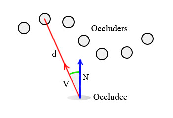
Given any pixel in the scene, it is possible to calculate its ambient occlusion by treating all neighboring pixels as small spheres, and adding together their contributions. To simplify things, we will work with points instead of spheres: occluders will be just points with no orientation and the occludee (the pixel which receives occlusion) will be a pair. Then, the occlusion contribution of each occluder depends on two factors:

씬에서 어떤 픽셀이 주어졌을 때, 작은 구들로써 모든 이웃된 픽셀들을 다루고 픽셀들의 기여도를 더함으로써 AO를 계산할 수 있다. 단순화 하기 위해서, 우리는 구 대신에 점으로 작업할 것이다. : 차폐물은 단지 방향없는 점들로 되어 있고 occludee(차폐를 당하는 픽셀)은 한쌍이 될 것이다. 각각의 차폐물의 차폐 기여정도는 두가지 요소에 의존된다.


  • Distance “d” to the occludee.
  • Angle between the occludee´s normal “N” and the vector between occluder and occludee “V”.
With these two factors in mind, a simple formula to calculate occlusion is: Occlusion = max( 0.0, dot( N, V) ) * ( 1.0 / ( 1.0 + d ) )

  • occludee까지의 거리 "d"
  • occludee의 노말 "N"과 occluder와 occludee 사이의 벡터 "V"의 각도.
이 두 요소를 가지고, 차폐를 계산하는 간단한 공식은 : Occlusion = max( 0.0, dot( N, V) ) * ( 1.0 / ( 1.0 + d ) ) 과 같다.


The first term, max( 0.0, dot( N,V ) ), works based on the intuitive idea that points directly above the occludee contribute more than points near it but not quite right on top. The purpose of the second term ( 1.0 / ( 1.0 + d ) ) is to attenuate the effect linearly with distance. You could choose to use quadratic attenuation or any other function, it´s just a matter of taste.
첫번째 부분인 max( 0.0, dot( N,V ) )은 occludee 바로 위의 점들은 근처의 점들보다 더 많은 영향력을 준다는 직관적인 아이디어를 기반으로한다. 두번째 부분인 ( 1.0 / ( 1.0 + d ) ) 목적은 거리에 선형적으로 효과를 감소시킨다. 당신은 이차 감소나 어떤 다른 함수든 입맛대로 사용할 수 있다.

Posted Image

The algorithm is very easy: sample a few neighbors around the current pixel and accumulate their occlusion contribution using the formula above. To gather occlusion, I use 4 samples (<1,0>,<-1,0>,<0,1>,<0,-1>) rotated at 45º and 90º, and reflected using a random normal texture.
알고리즘은 매우 쉽다: 현재 픽셀 주변에 몇개의 이웃들을 샘플링하고 위의 공식을 사용해서 차폐 기여값을 누적시킨다. 차폐값을 모으기 위해 나는 45도, 90도 회전되고 랜덤 노말 텍스쳐를 사용해 반사된 부분에 대해 (<1,0>,<-1,0>,<0,1>,<0,-1>) 4 샘플링을 사용한다.


Some tricks can be applied to accelerate the calculations: you can use half-sized position and normal buffers, or you can also apply a bilateral blur to the resulting SSAO buffer to hide sampling artifacts if you wish. Note that these two techniques can be applied to any SSAO algorithm.

계산을 가속화하기 위해서 몇가지 트릭을 적용할 수 있다. : 절반의 사이즈의 위치, 노말 버퍼를 사용할 수 있거나, 원한다면 샘플링된 것의 결함을 숨기기 위해 SSAO 버퍼의 결과에 블러(양쪽 방향에 대한 블러인듯)를 적용할 수 있다. 이 두가지 테크닉은 어떠한 SSAO 알고리즘에도 적용할 수 있다.

This is the HLSL pixel shader code for the effect that has to be applied to a full screen quad:
이것은 풀 스크린 사각형에 적용될 효과에 대한 HLSL 픽셀 쉐이더 코드이다.

sampler g_buffer_norm;
sampler g_buffer_pos
;
sampler g_random
;
float random_size;
float g_sample_rad;
float g_intensity;
float g_scale;
float g_bias;

struct PS_INPUT
{
float2 uv
: TEXCOORD0;
};

struct PS_OUTPUT
{
float4 color
: COLOR0;
};

float3 getPosition
(in float2 uv)
{
return tex2D(g_buffer_pos,uv).xyz;
}

float3 getNormal
(in float2 uv)
{
return normalize(tex2D(g_buffer_norm, uv).xyz * 2.0f - 1.0f);
}

float2 getRandom
(in float2 uv)
{
return normalize(tex2D(g_random, g_screen_size * uv / random_size).xy * 2.0f - 1.0f);
}

float doAmbientOcclusion(in float2 tcoord,in float2 uv, in float3 p, in float3 cnorm)
{
float3 diff
= getPosition(tcoord + uv) - p;
const float3 v = normalize(diff);
const float d = length(diff)*g_scale;
return max(0.0,dot(cnorm,v)-g_bias)*(1.0/(1.0+d))*g_intensity;
}

PS_OUTPUT main
(PS_INPUT i)
{
PS_OUTPUT o
= (PS_OUTPUT)0;

o
.color.rgb = 1.0f;
const float2 vec[4] = {float2(1,0),float2(-1,0),
                        float2
(0,1),float2(0,-1)};

float3 p
= getPosition(i.uv);
float3 n
= getNormal(i.uv);
float2 rand
= getRandom(i.uv);

float ao = 0.0f;
float rad = g_sample_rad/p.z;

//**SSAO Calculation**//
int iterations = 4;
for (int j = 0; j < iterations; ++j)
{
  float2 coord1
= reflect(vec[j],rand)*rad;
  float2 coord2
= float2(coord1.x*0.707 - coord1.y*0.707,
                          coord1
.x*0.707 + coord1.y*0.707);
 
  ao
+= doAmbientOcclusion(i.uv,coord1*0.25, p, n);
  ao
+= doAmbientOcclusion(i.uv,coord2*0.5, p, n);
  ao
+= doAmbientOcclusion(i.uv,coord1*0.75, p, n);
  ao
+= doAmbientOcclusion(i.uv,coord2, p, n);
}
ao
/=(float)iterations*4.0;
//**END**//

//Do stuff here with your occlusion value “ao”: modulate ambient lighting, write it to a buffer for later //use, etc.
return o;
}

The concept is very similar to the image space approach presented in “Hardware Accelerated Ambient Occlusion Techniques on GPUs” [1] the main differences being the sampling pattern and the AO function. It can also be understood as an image-space version of “Dynamic Ambient Occlusion and Indirect Lighting” [2] Some details worth mentioning about the code:
이 개념은 “Hardware Accelerated Ambient Occlusion Techniques on GPUs” [1]에 설명된 이미지 공간에 접근하는 것과 매우 유사하고 샘플링되는 패턴과 AO 함수가 다르다. “Dynamic Ambient Occlusion and Indirect Lighting” [2] 의 Screen Space 버전으로써 이해할 수도 있다. 코드에 대해서 몇가지 디테일한 중요한 언급은 :


  • The radius is divided by p.z, to scale it depending on the distance to the camera. If you bypass this division, all pixels on screen will use the same sampling radius, and the output will lose the perspective illusion.
  • During the for loop, coord1 are the original sampling coordinates, at 90º. coord2 are the same coordinates, rotated 45º.
  • The random texture contains randomized normal vectors, so it is your average normal map. This is the random normal texture I use:

    Posted Image 

    It is tiled across the screen and then sampled for each pixel, using these texture coordinates:

    g_screen_size * uv / random_size 

    Where “g_screen_size” contains the width and height of the screen in pixels and “random_size” is the size of the random texture (the one I use is 64x64). The normal you obtain by sampling the texture is then used to reflect the sampling vector inside the for loop, thus getting a different sampling pattern for each pixel on the screen. (check out “interleaved sampling” in the references section)

  • 반지름은 카메라와의 거리에 의존하여 크기를 조절하기 위해 p.z로 나눈다. 만약 이 나누기 계산을 무시한다면 화면에 있는 모든 픽셀들은 같은 샘플링 반지름을 가질것이고, 결과물은 원근법을 잃게 될 것이다.
  • 루프를 도는 동안, coord1은 90도에 있는 원본 샘플링 좌표고 coord2는 45도 회전된 같은 좌표이다.
  • 랜덤 텍스쳐는 임의의 노말 벡터들을 포함하고 있어 평균 노말 맵이라 할 수 있다. 이것은 내가 사용하는 랜덤 노말 텍스쳐이다.:

    Posted Image 

    스크린에 걸쳐 타일링이 되고 이것들은 텍스쳐 좌표를 사용하여 각 픽셀로 샘플링된다. 

    g_screen_size * uv / random_size  

    g_screen_size는 화면의 너비와 높이를 포함하고 random_size는 랜덤 텍스쳐의 크기이다.(나는 64x64짜리를 사용한다). 텍스쳐가 샘플링 되는것에 의해 얻어지는 노말은 루프안에서 샘플링된 벡터를 반사하는데 사용되고, 따라서 화면에서 각 픽셀에 다른 샘플링된 패턴을 얻는다. (레퍼런스 색션에서 "interleaved sampling"을 확인해봐라.)


    At the end, the shader reduces to iterating trough some occluders, invoking our AO function for each of them and accumulating the results. There are four artist variables in it:


    결국에는, 쉐이더는 일부 occluder를 반복하는 것과 각각에 우리의 AO 함수를 적용하고, 결과를 누적하는 것을 줄여준다. 쉐이더에는 아티스트가 잡아줄 4개의 변수가 있다.


  • g_scale: scales distance between occluders and occludee.
  • g_bias: controls the width of the occlusion cone considered by the occludee.
  • g_sample_rad: the sampling radius.
  • g_intensity: the ao intensity.

  • g_scale: occluder와 occludee 사이에 거리의 크기를 정한다.
  • g_bias: occludee에 의해 고려되는 콘모양 차폐물의 너비를 조절한다.
  • g_sample_rad: 샘플링 반지름 범위
  • g_intensity: AO 정도(강함 정도)


Once you tweak the values a bit and see how the AO reacts to them, it becomes very intuitive to achieve the effect you want. 

값들을 조금씩 바꿔보고 그것들이 AO에 어떻게 영향을 끼치는지 보라, 원하는 효과를 얻기 위해서는 매우 직관적으로 되야한다.

Results

Posted Image
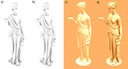
a) raw output, 1 pass 16 samples b] raw output, 1 pass 8 samples c) directional light only d) directional light – ao, 2 passes 16 samples each.


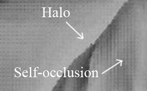
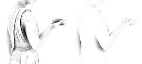
As you can see, the code is short and simple, and the results show no self occlusion and very little to no haloing. These are the two main problems of all the SSAO algorithms that use only the depth buffer as input, you can see them in these images:

보다시피 코드는 짧고 간단하고, 결과물은 self occlusion을 보여주지 않고 haloing을 거의 보여주지 않는다. 입력으로 오직 깊이 버퍼만 사용하는 모든 SSAO 알고리즘의 두가지 주요한 문제가 있다. 이 이미지에서 그것들을 볼 수 있다. :


Posted Image Posted Image


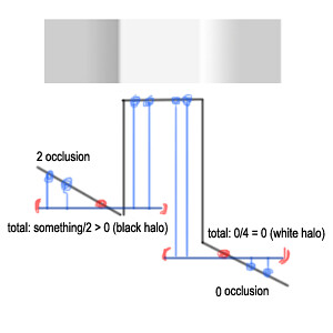
The self-occlusion appears because the traditional algorithm samples inside a sphere around each pixel, so in non-occluded planar surfaces at least half of the samples are marked as ‘occluded’. This yields a grayish color to the overall occlusion. Haloing causes soft white edges around objects, because in these areas self-occlusion does not take place. So getting rid of self-occlusion actually helps a lot hiding the halos.


The resulting occlusion from this method is also surprisingly consistent when moving the camera around. If you go for quality instead of speed, it is possible to use two or more passes of the algorithm (duplicate the for loop in the code) with different radiuses, one for capturing more global AO and other to bring out small crevices. With lighting and/or textures applied, the sampling artifacts are less apparent and because of this, usually you should not need an extra blurring pass.

전통적인 알고리즘은 각 픽셀 주변의 구안에서 샘플링이되서 샘플의 최소한 절반정도 차폐되지 않은 평면 표면도 차폐되었다고 표시되기 때문에 self occlusion이 나타난다. 이것은 차폐 전반에 회색조의 색을 나타내게한다. haloing은 오브젝트 주변에 부드러운 흰색 모서리로 나타나는데 이 영역안에서는 self occlusion이 일어나지 않기 때문이다.  self occlusion를 제거하는 것은 사실상 많은 haloing을 제거하는것에 도움을 준다.

이 방법으로부터의 차폐 결과는 또한 놀랍게도 카메라가 주변으로 이동할때도 일정하다. 만약 속도 대신에 퀄리티를 원한다면, 한번은 전역 AO를 위해서 나머지는 작은 틈을 가져오기 위해서 다른 반지름으로 두번 혹은 더 많은 패스(코드상에서 루프를 위해 중복되는)로 알고리즘을 사용할 수 있다. 조명 and/or 텍스쳐를 적용하면, 샘플링된 흠집들은 이 방법 때문에 적게 보여지고 보통 추가적인 블러 패스가 필요없다.


Taking it further 

I have described a down-to-earth, simple SSAO implementation that suits games very well. However, it is easy to extend it to take into account hidden surfaces that face away from the camera, obtaining better quality. Usually this would require three buffers: two position/depth buffers (front/back faces) and one normal buffer. But you can do it with only two buffers: store depth of front faces and back faces in red and green channels of a buffer respectively, then reconstruct position from each one. This way you have one buffer for positions and a second buffer for normal. 

나는 게임들에 매우 적합한 간단한 SSAO 구현을 실제적으로 설명하고 있다. 그러나, 더 나은 퀄리티를 얻기 위해서 카메라로 부터 면이 떨어진 은면들을 고려하기 위해서 구현을 확장하는 것은 쉽다. 보통 이것은 세개의 버퍼를 필요로한다. : 두개의 위치/깊이 버퍼(앞면/뒷면) 그리고 하나의 노말 버퍼이다. 그러나 오직 두개의 버퍼를 가지고 할 수 있다. : 앞면과 뒷면의 깊이를 빨간색, 초록색 채널에 각각 저장하고 각각으로 부터 위치를 재구축한다. 이 방법으로 당신은 위치를 위한 하나의 버퍼와 노말을 위한 버퍼를 가진다.

These are the results when taking 16 samples for each position buffer: 

각 위치 버퍼에 대해서 16 샘플링을 한 결과가 있다.

Posted Image
left: front faces occlusion, right: back faces occlusion

To implement it just and extra calls to “doAmbientOcclusion()” inside the sampling loop that sample the back faces position buffer when searching for occluders. As you can see, the back faces contribute very little and they require doubling the number of samples, almost doubling the render time. You could of course take fewer samples for back faces, but it is still not very practical.

이것을 구현하기 위해서 occluder를 찾을 때 뒷면 위치 버퍼를 샘플링하는 샘플링 루프 안에서 여분의 "doAmbientOcclusion()"함수를 호출해준다. 보시다시피, 뒷면은 매우 약간의 영향을 끼쳐서 샘플링 숫자를 두배로 올릴 필요가 있고 렌더링때 거의 두배로 올린다. 물론 뒷면에 더 적은 샘플링을 취할수는 있지만 실용적이지는 않다.

This is the extra code that needs to be added:

이것은 추가될 필요가 있는 여분의 코드이다:


inside the for loop, add these calls:

루프안에 이것들의 호출을 추가하라.

ao += doAmbientOcclusionBack(i.uv,coord1*(0.25+0.125), p, n);
ao
+= doAmbientOcclusionBack(i.uv,coord2*(0.5+0.125), p, n);
ao
+= doAmbientOcclusionBack(i.uv,coord1*(0.75+0.125), p, n);
ao
+= doAmbientOcclusionBack(i.uv,coord2*1.125, p, n);


Add these two functions to the shader:

이 두 함수를 쉐이더에 추가하라.

float3 getPositionBack(in float2 uv)
{
return tex2D(g_buffer_posb,uv).xyz;
}
float doAmbientOcclusionBack(in float2 tcoord,in float2 uv, in float3 p, in float3 cnorm)
{
float3 diff
= getPositionBack(tcoord + uv) - p;
const float3 v = normalize(diff);
const float d = length(diff)*g_scale;
return max(0.0,dot(cnorm,v)-g_bias)*(1.0/(1.0+d));
}


Add a sampler named “g_buffer_posb” containing the position of back faces. (draw the scene with front face culling enabled to generate it) Another small change that can be made, this time to improve speed instead of quality, is adding a simple LOD (level of detail) system to our shader. Change the fixed amount of iterations with this: 

뒷면의 위치를 포함할 "g_buffer_posb"라는 이름의 샘플러를 추가하라. (앞면 컬링을 하고 씬을 그리면 생성할 수 있다.) 퀄리티보다 속도를 향상시키기 위해서 이번에 해볼수 있는 또 하나의 작은 변화는 우리의 쉐이더에 간단한 LOD 시스템을 추가하는 것이다. 이것으로 반복의 고정된 횟수를 변경하라.

int iterations = lerp(6.0,2.0,p.z/g_far_clip); 

The variable “g_far_clip” is the distance of the far clipping plane, which must be passed to the shader. Now the amount of iterations applied to each pixel depends on distance to the camera. Thus, distant pixels perform a coarser sampling, improving performance with no noticeable quality loss. I´ve not used this in the performance measurements (below), however.

변수 "g_far_clip"은 원단면 클리핑 평면의 거리이고, 쉐이더에 전달해야만 한다. 이제는 각각의 픽셀에 적용되는 반복의 횟수는 카메라의 거리에 의존한다. 따라서 멀리 떨어져 있는 픽셀은 더 거칠게 샘플링 되고 알아볼정도의 퀄리티 손실 없이 퍼포먼스를 향상된다. 그러나 나는 퍼포먼스 측정때 이것을 사용하지는 않았다.

Conclusion and Performance Measurements

As I said at the beginning of the article, this method is very well suited for games using deferred lighting pipelines because it requires two buffers that are usually already available. It is straightforward to implement, and the quality is very good. It solves the self-occlusion issue and reduces haloing, but apart from that it has the same limitations as other screen-space ambient occlusion techniques: Disadvantages:

이 아티클의 시작때 내가 말했듯이, 이 방법은 보통 이미 이용할 수 있는 두 버퍼를 필요로 하기 때문에 디퍼드 라이팅 파이프라인을 사용하는 게임에 매우 적합하다. 이 방법은 구현하기 쉽고 퀄리티도 매우 좋다. 이 방법은 self occlusion 이슈를 해결하고 haloing을 줄여준다. 하지만 다른 SSAO 테크닉들과 같은 제한은 있다:

단점 :

  • Does not take into account hidden geometry (especially geometry outside the frustum).
  • The performance is very dependent on sampling radius and distance to the camera, since objects near the front plane of the frustum will use bigger radiuses than those far away.
  • The output is noisy.

  • 숨겨진 지오메트리를 고려하지 않는다.(특히 절두체 밖의 지오메트리)
  • 퍼포먼스는 샘플링 반지름과 카메라의 거리에 매우 의존적이고 절두체의 앞 평면 근처의 오브젝트들은 멀리 있는 것들 보다 더 큰 반지름을 사용할 것이다.
  • 결과물은 노이즈가 있다.

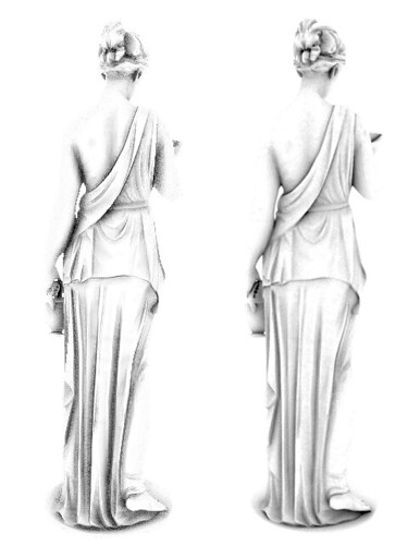
Speed wise, it is roughly equal to a 4x4 Gaussian blur for a 16 sample implementation, since it samples only 1 texture per sample and the AO function is really simple, but in practice it is a bit slower. Here´s a table showing the measured speed in a scene with the Hebe model at 900x650 with no blur applied on a Nvidia 8800GT:

속도면에서 16 샘플링 구현을 위한 4x4 가우시안 블러와 거의 동일하고 샘플링당 텍스쳐 1장씩만 들고 AO 함수도 정말 간단하지만 실용적인 면에서는 조금 느리다. 여기 Nvidia 8800GT에서 블러 없이 900x650 해상도에서 Hebe 모델을 띄운 씬의 속도를 측정한 표를 보자.

In these last screenshots you can see how this algorithm looks when applied to different models. At highest quality (32 samples front and back faces, very big radius, 3x3 bilateral blur):

이 마지막 스크린샷들에서 다른 모델에 적용되었을 때 이 알고리즘이 어떻게 보이는지 알 수 있을 것이다. 가장 높은 퀄리티(앞면, 뒷면 32 샘플링, 매우 큰 반지름, 3x3 블러 적용)


Posted Image


At lowest quality (8 samples front faces only, no blur, small radius):
가장 낮은 퀄리티(앞면 8 샘플링, 블러 없음, 작은 반지름)

Posted Image


It is also useful to consider how this technique compares to ray-traced AO. The purpose of this comparison is to see if the method would converge to real AO when using enough samples.

레이 트레이싱 기반의 AO와 이 기술을 비교하면 어떤지 고려하는데도 유용하다. 이 비교의 목적은 충분한 샘플링을 사용했을 때 이 방법이 실제 AO와 근접하게 모이는지를 보는 것이다.

Posted Image
Left: the SSAO presented here, 48 samples per pixel (32 for front faces and 16 for back faces), no blur. Right: Ray traced AO in Mental Ray. 32 samples, spread = 2.0, maxdistance = 1.0; falloff = 1.0.


One last word of advice: don´t expect to plug the shader into your pipeline and get a realistic look automatically. Despite this implementation having a good performance/quality ratio, SSAO is a time consuming effect and you should tweak it carefully to suit your needs and obtain the best performance possible. Add or remove samples, add a bilateral blur on top, change intensity, etc. You should also consider if SSAO is the way to go for you. Unless you have lots of dynamic objects in your scene, you should not need SSAO at all; maybe light maps are enough for your purpose as they can provide better quality for static scenes.

마지막 충고 : 당신의 파이프라인에 이 쉐이더를 붙인다고해서 자동적으로 실제와 같이 보이는 퀄리티를 기대하지 말아라. 이 구현은 좋은 퍼포먼스와 퀄리티를 가짐에도 불구하고 SSAO는 시간을 소비하는 효과라서 당신의 요구에 맞추면서 가능한 가장 좋은 퍼포먼스를 얻기 위해서 주의를 기울여야 한다. 샘플링을 추가하거나 제거하고 위에 블러링을 추가하고 밀도 정도치를 변경하는 등등. 당신은 SSAO가 당신을 위한 길인지에 대해서도 고려해봐야 한다. 당신이 씬에 동적인 오브젝트들을 많이 가지고 있지 않다면 SSAO가 전혀 필요하지 않다; 아마도 정적인 씬을 위해 더 좋은 퀄리티를 제공하기 위해서 라이트 맵은 당신의 목적에 충분할 것이다.

I hope you will benefit in some way from this method. All code included in this article is made available under the MIT license 

References

[1] Hardware Accelerated Ambient Occlusion Techniques on GPUs
(Perumaal Shanmugam) [2] Dynamic Ambient Occlusion and Indirect Lighting
(Michael Bunnell) 

[3] Image-Based Proxy Accumulation for Real-Time Soft Global Illumination
(Peter-Pike Sloan, Naga K. Govindaraju, Derek Nowrouzezahrai, John Snyder) 

[4] Interleaved Sampling
(Alexander Keller, Wolfgang Heidrich) 

Posted Image
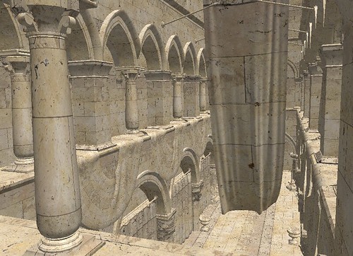
Crytek´s Sponza rendered at 1024x768, 175 fps with a directional light.

Posted Image
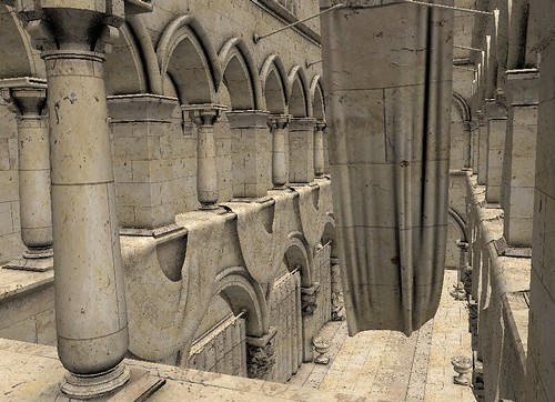
The same scene rendered at 1024x768, 110 fps using SSAO medium settings: 16 samples, front faces, no blur. Ambient lighting has been multiplied by (1.0-AO).

The Sponza model was downloaded from Crytek's website.


About the Author(s)

José María Méndez is a 23 year old computer engineering student. He has been writing amateur games for 6 years and is currently working as lead programmer at a startup company called Minimal Drama Game Studio.

반응형
Posted by msparkms
,
반응형

http://en.wikipedia.org/wiki/Deferred_shading

Deferred shading         From Wikipedia, the free encyclopedia

컴퓨터 그래픽스에서 디퍼드 렌더링은 쉐이더의 결과를 색상 프레임 버퍼에 즉시 쓰는 대신에 나중에 합쳐지기 위한 중간 저장버퍼에(G-Buffer 불리는) 쓰는  작은 파트로 나누고 계산되어 지는 쉐이딩 알고리즘 중에 하나인 삼차원 쉐이딩 기술이다. 현대 하드웨어의 구현은 불필요한 버텍스 변환을 피하기 위해 멀티 렌더 타겟(MRT) 사용하는 경향이 있다. 보통 한번에 필요로 하는 버퍼들은 쉐이딩 알고리즘에(예를들면 조명 방정식읽어질때(보통 입력 텍스쳐로만들어지고 최종 결과를 생성하기 위해 합쳐진다. 이러한 방식의 씬의 음영을 위한 계산과 메모리 대역폭은 가시적인 부분을 줄여지고 음영이 지는 깊이 복잡도는 줄어든다.


Advantages


디퍼드 쉐이딩의 주요한 장점은 조명으로 부터의 기하요소의 중복을 제거하는 것이다. 오직 한번의 지오메트리 패스를 필요로 하고 각각의 조명은 오직 실제 적용되는 픽셀들만 계산되어진다. 이것은 분명한 퍼포먼스 부하없이 씬에 많은 조명을 렌더링 있게 해준다. 진입부에 말한 다른 장점들도 있다. 이러한 장점들은 복잡한 조명 자원들의 관리를 간단하게 해주는 것과 다른 복잡한 쉐이더 자원 관리의 용이성, 소프트웨어 렌더링 파이프라인의 간략화를 포함한다.


Disadvantages


디퍼드 렌더링의 단점중 중요한 한가지는 알고리즘안에서 투명도를 다룰 없다는 것이다. 비록 문제가 Z-버퍼 씬에서는 일반적인 것이고 씬에서 투명한 부분의 렌더링을 늦추고 정렬하는 것에 의해 조절되는 경향이 있다고 할지라도. 깊이 필링은 디퍼드 렌더링에서 순서-독립적 투명도를 성취하기 위해 사용되어 있다. 그러나 추가적인 배치와 G-버퍼 크기의 비용이 있다. 다이렉트X 10 이후 버전을 지원하는 현재 하드웨어는 종종 상호적인 프레임율을 유지하기 위해서 충분히 빠른 배치들을 처리할 있다. 순서-독립적 투명도에 디퍼드 쉐이딩을 원할때는 같은 기법을 사용하는 포워드 쉐이딩보다 효과적이지 않다.

또다른 중요한 단점은 다중 머트리얼을 사용하기 어렵다는 것이다. 많은 다른 머트리얼들을 사용하는 것은 가능하지만 이미 크고 많은 양의 메모리 대역폭을 먹고 있는 G-버퍼에 많은 데이터의 저장을 요구한다.

기하 스테이지로부터 조명 스테이지가 분리되었기 때문에 생긴  중요한 단점중 하나인 하드웨어 안티 얼라이어싱은 이상 올바른 결과를 얻지 못한다. : 비록 기본 속성(디퓨즈, 노말 ) 렌더링할 사용되어지는 첫번째 패스는 안티 얼라이어싱을 사용할 있지만 안티 얼라이어싱을 필요로하는 전체 조명까지는 아니다. 제한을 극복하기 위한 보통의 기법중 하나는 마지막 이미지에 외곽선 추출을 하고 외곽선에 블러를 적용하는것이다. 하지만 최근에 고급의 -처리-외곽선-보정 기법이 개발되었다MLAA[5] (Killzone 3Dragon Age 2, 등등), FXAA[6] (Crysis 2FEAR 3Duke Nukem Forever), SRAA,[7] DLAA[8] (Star Wars: The Force Unleashed II), post MSAA (Crysis 2에서 디폴트 안티 얼라이어싱 기법). 하나의 유명한 기법은 Halo Reach에서 사용된 시간적-안티 얼라이어싱이다. 다이렉트X 10 디퍼디 쉐이딩에서 안티 얼라이어싱이 하드웨어에서 가능하게 멀티 샘플링된 렌더 타겟(10.1 버전에서는 깊이 버퍼도)에서 각각의 샘플에 접근하는 쉐이더의 기능을 소개했다이전 하드웨어에서 안티 얼라이어싱의 어떠한 이점을 잃게 할지도 모르지만  기능은 어떠한 경우에는 바람직한 안티 얼라이어싱의 형태를 만들어 주고 안티 얼라이어싱된 외곽선에 HDR 휘도 매핑을 정확하게 적용할 있게 해준다.


Deffered Lighting


디퍼드 라이팅은 (또한 -패스 조명이라 알려져 있는) 디퍼드 쉐이딩의 수정판이다. 기법은 디퍼드 쉐이딩에서 패스를 쓰던것 대신에 쓰리 패스를 사용한다. 기하요소가 넘어가는 첫번째 패스에서는 오직 픽셀당 조명(조도) 계산하기 위해 필요한 속성들만 G-버퍼에 쓴다. 오직 디퓨즈와 스페큘러 조명 데이터 출력후에 지연된 패스인 두번째 스크린-공간 패스는 조명 데이터와 최종 픽셀당 쉐이딩 출력값을 읽어와서 씬을 만들어야 한다. 디퍼드 라이팅의 분명한 장점은 G-버퍼의 크기를 극적으로 줄이는 것이다. 분명한 비용은 한번 대신 두번 기하구조를 렌더링할 필요가 있다는 것이다. 추가적인 비용은 디퍼드 쉐이딩에서의 디퍼드 패스는 오직 하나의 합쳐진 조도 값을 필요로 했지만 디퍼드 라이팅에서 디퍼드 패스는 디퓨즈와 스페큘러 조도를 분리해서 출력해야만 한다는 것이다. ( 부분은 기법을 조사해 봐야 정확하게 해석할 있겠음 -0-;;;)

G-버퍼의 크기를 줄여주기 때문에 기법은 부분적으로 디퍼드 쉐이딩의 심각한 단점을 극복할 있다. - 다중 머트리얼. 해결할 있는 하나의 문제는 MSAA이다. 디퍼드 라이팅은 DX9 하드웨어에서 MSAA 함께 사용될 있다.


Deferred lighting in commercial games

기법은 비디오 게임에서 많은 양의 동적 조명을 사용하고 필요한 쉐이더 명령의 복잡도를 줄여주는 기능을 컨트롤하기 때문에 사용이 증가되고 있다. 디퍼드 라이팅을 사용하는 게임의 몇가지 예를 들면 :

§  Alan Wake

§  Bioshock Infinite[11]

§  Blur

§  Brink

§  Crackdown and Crackdown 2[12]

§  Crysis 2[13]

§  Dead Space[14] and Dead Space 2[15]

§  Deus Ex: Human Revolution [16]

§  Grand Theft Auto IV

§  Halo: Reach [17]

§  inFamous and inFamous 2[18]

§  LittleBigPlanet and LittleBigPlanet 2[19]

§  Shift 2 UNLEASHED [20]

§  Stalker: Shadow of ChernobylClear Sky and Call of Prypiat[21]

§  Red Dead Redemption

§  Resistance series[22]

§  StarCraft II [23]

§  Uncharted and Uncharted 2[24]

§  Vanquish [25]

Deferred shading in commercial games

디퍼드 라이팅의 비교에서 기법은 높은 메모리 크기와 대역폭의 요구 때문에 매우 대중적이지는 않다. 특히 메모리 크기와 대역폭에 매우 제한적이고 자주 버틀넥이 걸리는 곳에서.


§  Battlefield 3[26]

§  Dungeons

§  Killzone 2 and Killzone 3[27]

§  Mafia 2

§  Metro 2033[28]

§  Rift

§  Shrek[29]

§  Splinter Cell: Conviction

§  Tabula Rasa[30]

§  Trine

§  Viva Pinata

§  Dota 2[31]


Deferred techniques in game engines

§  CryEngine 3 [32]

§  I-Novae [33]

§  Unity [34]

§  Frostbite 2 [35]

§  Unreal Engine 3 [36]

§  Chrome Engine

§  GameStart [37]


History

디퍼드 쉐이딩의 아이디어는 Michael Deering The triangle processor and normal vector shader: a VLSI system for high performance graphics 1998년도에 이름 붙여진 그의 대학 논문에서 소개되었다. 비록 논문은 "지연된"이라는 단어를 사용하지는 않았지만 중요한 컨셉은 소개되었다 : 픽셀은 깊이 해상도 후에 한번 음영 처리가 된다. G-버퍼를 사용하는 오늘날 우리에게 알려진 디퍼드 쉐이딩은 1990년에 Saito Takahashi 논문에 의해 소개되었다. 비록

들도 "지연된"이란 단어를 사용하지는 않았지만 말이다. 2004 그래픽 하드웨어 제품에서 구현을 시작으로 나타났다. 기법은 비디오 게임과 같은 프로그램에서 유명세를 얻었고 마침내 2008년에서 2010년에 메인 스트림이 되었다.


References

1.    ^ http://thecansin.com/Files/Deferred%20Rendering%20in%20XNA%204.pdf

2.    ^ "NVIDIA SDK 9.51 - Featured Code Samples". NVIDIA. 2007-01-17. Retrieved 2007-03-28.

3.    ^ http://diaryofagraphicsprogrammer.blogspot.com/2008/03/light-pre-pass-renderer.html

4.    ^ "Deferred shading tutorial". Pontifical Catholic University of Rio de Janeiro. Retrieved 2008-02-14.

5.    ^ http://igm.univ-mlv.fr/~biri/mlaa-gpu/TMLAA.pdf

6.    ^ http://www.ngohq.com/images/articles/fxaa/FXAA_WhitePaper.pdf

7.    ^ http://research.nvidia.com/publication/subpixel-reconstruction-antialiasing

8.    ^ http://and.intercon.ru/releases/talks/dlaagdc2011/

9.    ^ http://and.intercon.ru/releases/talks/dlaagdc2011/slides/

10.  ^ http://www.realtimerendering.com/blog/deferred-lighting-approaches/

11.  ^ http://gamer.blorge.com/2010/11/21/bioshock-infinite-development-is-ps3-focused-and-uses-uncharted-2-tech/

12.  ^ http://www.eurogamer.net/articles/digitalfoundry-crackdown2-tech-interview

13.  ^ http://www.slideshare.net/guest11b095/a-bit-more-deferred-cry-engine3

14.  ^ "Dead Space by Electronic Arts". NVIDIA. Retrieved 2008-02-14.

15.  ^ "Face-Off: Dead Space 2". Retrieved 2010-02-01.

16.  ^ http://translate.google.com/translate?hl=en&sl=ja&tl=en&u=http%3A%2F%2Fgame.watch.impress.co.jp%2Fdocs%2Fseries%2F3dcg%2F20100922_395310.html

17.  ^ http://www.eurogamer.net/articles/digitalfoundry-halo-reach-tech-interview

18.  ^ http://gamer.blorge.com/2010/11/21/bioshock-infinite-development-is-ps3-focused-and-uses-uncharted-2-tech/

19.  ^ http://www.digitalscrutiny.com/content/2011/01/littlebigplanet-2-tech-analysis/

20.  ^ http://www.eurogamer.net/articles/digitalfoundry-the-making-of-shift-2?page=2

21.  ^ Shishkovtsov, Oles (2005-03-07). "GPU Gems 2: Chapter 9. Deferred Shading in S.T.A.L.K.E.R"Nvidia. Retrieved 2011-02-02.

22.  ^ http://cmpmedia.vo.llnwd.net/o1/vault/gdc09/slides/gdc09_insomniac_prelighting.pdf

23.  ^ "StarCraft II Effects & techniques" (PDF). AMD. Retrieved 2010-02-28.

24.  ^ http://features.cgsociety.org/story_custom.php?story_id=5545

25.  ^ http://platinumgames.com/tag/deferred-rendering/

26.  ^ http://www.slideshare.net/DICEStudio/spubased-deferred-shading-in-battlefield-3-for-playstation-3

27.  ^ http://www.guerrilla-games.com/publications/dr_kz2_rsx_dev07.pdf

28.  ^ http://www.eurogamer.net/articles/digitalfoundry-tech-interview-metro-2033?page=2

29.  ^ "History - Electric Sheep Games". Retrieved 14 April 2011.

30.  ^ "Deferred shading in Tabula Rasa". NVIDIA. Retrieved 2008-02-14.

31.  ^ "Valve Developer Wiki - Dota 2". Retrieved 10 April 2012.

32.  ^ "CryENGINE 3 Specifications". Crytek GmbH. Retrieved 2009-03-12.[dead link]

33.  ^ "Infinity Development Journal – Deferred Lighting". I-Novae Studios. 2009-04-03. Retrieved 2011-01-26.

34.  ^ Vosburgh, Ethan (2010-09-09). "Unity 3 Feature Preview – Deferred Rendering". Unity Technologies. Retrieved 2011-01-26.

35.  ^ "Lighting you up in Battlefield 3"DICE. March 3, 2011. Retrieved September 15, 2011.

36.  ^ "Unreal Engine 3 Showcase - Samaritan". Epic Games. 2011-03-10. Retrieved 2011-07-07.

37.  ^ "GameStart – Feature List".

38.  ^ Deering, Michael; Stephanie Winner, Bic Schediwy, Chris Duffy, Neil Hunt. "The triangle processor and normal vector shader: a VLSI system for high performance graphics". ACM SIGGRAPH Computer Graphics (ACM Press) 22 (4): 21–30.

39.  ^ Saito, Takafumi; Tokiichiro Takahashi (1990). "Comprehensible rendering of 3-D shapes". ACM SIGGRAPH Computer Graphics (ACM Press) 24 (4): 197–206. doi:10.1145/97880.97901.

40.  ^ "Deferred Shading" (PDF). NVIDIA. Retrieved 2007-03-28.

41.  ^ Klint, Josh. Deferred Rendering in Leadwerks Engine. Leadwerks.


See also

§  S.T.A.L.K.E.R.

§  Leadwerks Engine

§  Rockstar Advanced Game Engine

§  Unity Engine

§  Havok Vision Engine


반응형
Posted by msparkms
,
반응형
http://www.codermind.com/articles/Raytracer-in-C++-Introduction-What-is-ray-tracing.html

raytracer output - global illumination - iso surfaces - hdr

This article is the foreword of a serie of article about ray tracing. It's probably a word that you may have heard without really knowing what it represents or without an idea of how to implement one using a programming language. This article and the following will try to fill that for you. Note that this introduction is covering generalities about ray tracing and will not enter into much details of our implementation. If you're interested about actual implementation, formulas and code please skip this and go to part one after this introduction.

이 아티클은 Ray tracing에 대한 아티클 시리즈중 서문이다. 아마도 Ray tracing이라는 단어는 무엇을 의미하는지 확실히 알지는 못하거나 프로그래밍 언어를 사용해서 어떻게 구현해야 할지 아이디어가 없더라도 들어는 봤을 것이다. 이 아티클과 다음에 나올 것들은 당신이 원하는 것을 채워줄 것이다. 이번 도입부는 Ray tracing에 대해서 우리가 할 구현의 많은 세부사항들은 시작하지 않을 것이고 일반적인 부분으로 구성하였다. 만약 실질적인 구현에 대해서 관심이 있다면 이 부분을 건너뛰고 이 도입부 뒤에 있는 내용으로 가서 공식과 코드를 보라.

What is ray tracing ?


Ray tracing is one of the numerous techniques that exist to render images with computers. The idea behind ray tracing is that physically correct images are composed by light and that light will usually come from a light source and bounce around as light rays (following a broken line path) in a scene before hitting our eyes or a camera. By being able to reproduce in computer simulation the path followed from a light source to our eye we would then be able to determine what our eye sees.

Ray tracing은 컴퓨터로 이미지들을 렌더링하기 위해 존재하는 수많은 기법들중 하나이다. Ray tracing의 아이디어는 물리적으로 올바른 상은 빛에 의해 구성된다는 것과 빛은 광원으로부터 나오고 씬 안에서 광선들은 우리 눈이나 카메라에 도달하기전에 산란한다(꺽인 선을 따라감)는 것이다.

Of course it's not as simple as it sounds. We need some method to follow these rays as the nature has an infinite amount of computation available but we have not. One of the most natural idea of ray tracing is that we only care about the rays that hit our eyes directly or after a few rebounds. The second idea is that our generated images will usually be grids of pixels with a limited resolution. Those two ideas together form the basis of most basic raytracers. We will place our point of view in a 3D scene, and we will shoot rays exclusively from this point of view and towards a representation of our 2D grid in space. We will then try to evaluate the amount of rebounds needed to go from the light source to our eye. This is mostly okay because the actual light simulation does not take into account the actual direction of the ray to be accurate. Of course it is a simplification we'll see later why.

물론 이것은 들리는 것 만큼 간단한 것은 아니다. 자연은 무한한 양의 계산을 할 수 있지만 우리는 그럴 수 없으므로 이 광선들을 따라갈 방법이 필요하다. Ray tracing의 자연적인 아이디어중 가장 중요한 것은 우리의 눈으로 바로 들어오는 광선이나 약간의 산란후에 들어오는 광선만 고려하면 된다는 것이다. 두번째 아이디어는 우리가 생성할 이미지들은 보통 제한된 해상도로 픽셀로 이루어진 격자라는 것이다. 이 두가지 아이디어 모두 대부분의 기초적인 Raytracer들의 기본이 되었다. 우리는 3D 씬으로 관점을 두어야 하고 이 관점으로 부터 광선을 쏘고 공간안의 2D 격자로 향하게 할 것이다. 그리고나서 우리는 광원에서 우리눈으로 오는데 필요한 재 산란된 양을 평가할 것이다. 이 방식은 일반적으로 괜찮다.  정확하게 말해서 실제 빛 시뮬레이션은 실제 광선의 방향을 고려하지는 않기 때문이다. 물론 우리가 나중에 알게될 단순화된 방법이다. 

How are raytracers used ?


The ideas behind ray tracing (in its most basic form) are so simple, we would at first like to use it everywhere. But it's not used everywhere.

Ray tracing의 배경이 되는 아이디어들은 매우 간단해서 우리는 처음에 모든 곳에 사용하고 싶어 한다. 하지만 모든 곳에서 사용되지는 않는다. 

Ray tracing has been used in production environment for off-line rendering for a few decades now. That is rendering that doesn't need to have finished the whole scene in less than a few milliseconds. Of course we should not generalize and let you know that several implementations of raytracer have been able to hit the "interactive" mark. Right now so called "real-time ray tracing" is a very active field right now, as it's been seen as the next big thing that 3D accelerators need to be accelerating. Raytracer are really liked in areas where the quality of reflections is important. A lot of effects that seem hard to achieve with other techniques are very natural using a raytracer. Reflection, refraction, depth of field, high quality shadows. Of course that doesn't necessarily mean they are fast.

Ray tracing은 현재 몇 십년동안 오프라인 렌더링으로 생산하는 환경에서 사용되어 왔다. 오프라인 렌더링에서는 몇 밀리세컨드보다 적은 시간에 완전한 씬을 완료할 필요가 없다. 물론 우리는 일반화 하지 않았고 "interactive" 하게 하려는 목표를 달성할 수 있는 raytracer의 몇몇가지의 구현방법들을 알지 못한다. 요즘에 "Real-time Ray tracing"이라 불리우는 분야가 매우 활성화되고 있어 3D 가속기의 가속을 필요로 하는것이 다음의 큰일로 보여지고 있다. Raytracer는 반사의 퀄리티가 중요한 곳에서 정말 환영받고 있다. 다른 기술들로는 성취하기 힘들어 보이는 많은 효과들은 raytracer를 사용하므로써 매우 자연스럽게 된다. 반사, 굴절, Depth of field, 고품질 그림자에서 사용된다. 물론 그것들이 빠르다는 것을 의미하는건 아니다.

Graphics card on the other hand they generate the majority of images these days but are very limited at ray tracing. Nobody can say if that limitation will be removed in the future but it is a strong one today. The alternative to ray tracing that graphics card use is rasterization. Rasterization has a different view on image generation. Its primitive is not rays, but it is triangles. For each triangle in the scene you would estimate its coverage on the screen and then for each visible pixel that is touched by a triangle you would compute its actual color. Graphics cards are very good at rasterization because they can do a lot of optimization related to this. Each triangle is drawn independently from the precedent in what we call an "immediate mode". This immediate mode knows only what the triangle is made of, and compute its color based on a serie of attributes like shader program, global constants, interpolated attributes, textures. A rasterizer would for example typically draw reflection using an intermediate pass called render to texture, a previous rasterizer pass would feed into itself, but with the same original limitations which then cause all kind of precision issues. This amnesia and several other optimizations are what allow the triangle drawing to be fast. Raytracing on the other hand doesn't forget about the whole geometry of the scene after the ray is launched. In fact it doesn't necessarily know in advance what triangles, or objects it will hit, and because of interreflexion they may not be constrained to a single portion of space. Ray tracing tends to be "global", rasterization tends to be "local". There is no branching besides simple decisions in rasterization, branching is everywhere on ray tracing.

반면에 그래픽카드는 요즘에 이미지들의 대다수를 생성하지만 Ray tracing에서는 제한적이다. 아무도 미래에 제한이 사라질 것이라고 말하지 않을 수 없지만 오늘날에는 아직 강한 제한이 있다. 그래픽카드에서 Ray tracing의 대안으로 래스터화를 사용한다. 래스터화는 이미지 생성에 다른 견해를 가진다. 이것의 원시 데이터는 광선이 아니라 삼각형이다. 씬 안에 있는 각각의 삼각형마다 화면안의 적용 범위를 추정하고 픽셀이 보이는지 여부를 판별하고 실제 색상을 계산해낸다. 그래픽카드들은 래스터화와 관련된 많은 최적화를 할 수 있었기 때문에 래스터화를 매우 능숙하다. 각각의 삼각형들은 "immediate mode"라 부르는것의 선례로 부터 독립적으로 그려진다. 이 즉시 모드는 오직 삼각형으로 구성되어있다고 알고있고 쉐이더 프로그램, 전역 상수, 속성의 보정, 텍스쳐들과 같은 일련의 속성들을 기반으로 색상을 계산한다. Rasterizer는 전형적인 예로 Render to Texture(이전의 Rasterizer 패스가 반영된)라 불리는 패스를 사용하여 반사를 그리지만 모든 정확도와 관련된 이슈들로 발생하는 근본적인 제한은 가지고 있다. 이런 기억상실증(그리지 않는 것을 말하는듯)과 몇가지 다른 최적화기법들은 삼각형을 빠르게 그릴 수 있게 해준다. 반면에 Raytracing은 광선이 발사된 후에 씬 전체의 Geometry에 대해서는 잊어버린다. 사실 삼각형이나 광선에 맞게될 오브젝트들이 무엇인지 미리 알 필요는 없다. 그것들의 상호반사는 부득이하게 공간의 한 위치에서 일어나지는 않을 것이기 때문이다. Raytracing은 "global"한 경향이 있고 Rasterization은 "local"한 경향이있다. Rasterization에서는 분기없이 간단한 결정을하지만 Raytracing에서는 모든곳에서 계산을 한다.

Ray tracing is not used everywhere in off line rendering either. The speed advantage of rasterization and other techniques (scan line rendering, mesh subdivision and fast rendering of micro facets) has often been hold against true "ray tracing solution", especially for primary rays. Primary rays are the one that hit the eye directly, instead of having rebound. Those primary rays are coherent and they can be accelerated with projective math (the attribute interpolation that fast rasterizers rely upon). For secondary ray (after a surface has been reflecting it, or refracting it), all bets are off because those nice properties disappear.

Raytracing은  Offline Rendering의 모든곳에서 사용되지는 않는다. Rasterization의 속도 이점과 다른 기술들(Scanline Rendering, 메쉬 분할, 소규모 면에 대한 빠른 렌더링)이 있어 종종 실제 "Raytracing 해법"을 특히 1차 광선들에서 나쁘게 보게되곤 한다. 1차 광선은 다시 튕겨나오는 것 대신에 눈으로 바로 들어오는 광선이다. 이 1차 광선들은 일관성 있고 투영 수학계산(빠른 Rasterizer들에 의존되는 속성의 보간)에 의해 가속될 수 있다. 2차 광선(표면에서 반사되거나 굴절된)에서는 멋진 성질이 사라지기 때문에 무효화 된다.

In the interest of full disclosure it should be noted that ray tracing maths can be used to generate data for rasterizer for example. Global illumination simulation may need to shoot ray to determine local properties such as ambiant occlusion or light bleeding. As long as the data is made local in the process that will be able to help a strict "immediate renderer".

알려져야할 밝혀진 사실들에서 흥미로운 점은 Raytracing 수학들은 Rasterizer의 예시를 만들기 위한 데이터를 생성하는대 사용될 수 있다는 것이다.  전역 조명 시뮬레이션은 Ambient occlusion이나 Light bleeding과 같은 지역적 성질을 결정하기 위해 광선을 발사할 필요가 있다. 데이터가 진행중에 지역적인 성질이 만들어지면 "immediate renderer"를 도울 수 있을 것이다.

Complications, infinity and recursion


Raytracers cannot and will not be a complete solution. No solution exist that can deal with true random infinity. It's often a trade off, trying to concentrate on what makes or break an image and its apparent realism. Even for off line renderer performance is important. It's hard to decide to shoot billions of rays per millions of pixel. Even if that's what the simulation seems to require. What trade offs do we need to do ? We need to decide to not follow every path possible.

Raytracer들은 완벽한 해법은 없다. 사실상 무한한 임의성을 다룰 수 있는 해법은 없다. 종종 이미지를 만들거나 깨뜨리는 것과 사실적으로 보이게 만드는 것중 어디에 집중하느냐에 따라 Trade off가 발생한다. 심지어 Offline Renderer에서조차 퍼포먼스는 중요하다. 몇백만 픽셀당 몇십억개의 광선을 발사하자고 결정하는건 어려운 일이다. 심지어 만약 그것이 시뮬레이션에서 요구되는 것을 보이게 하더라도 말이다. Trade off를 진행하기 위해 우리가 필요로 하는 일은 무엇인가? 우리는 가능한 모든 경로를 따라가게끔 결정하지 않을 필요가 있다.

Global illumination is a good example. In global illumination techniques such as photon mapping, we try to shorten the path between the light and the surface we're on. In all generality, doing full global illumination would require to cast infinite amount of ray in all the directions and see which percentage hit the light. We can do that but it's going to be very slow, instead, we'll first cast photons (using the exact same algorithm as ray tracing but in reverse from the light point of view) and see what surface they hit. Then we use that information to compute lighting in first approximation at each surface point. We only follow a new ray if we can have a good idea using a couple of rays (perfect reflection needs only one additional ray). Even then it can be expensive, as the tree of rays expands at a geometric rate. We have often to limit ourself to a maximum depth recursion.

전역 조명은 좋은 예시가 된다. Photon Mapping과 같은 전역조명 기술에서 우리는 빛과 우리가 보는 표면과의 경로를 짧게 하려고 한다. 일반적으로 전체 전역 조명을 하는 것은 모든 방향에 대해서 광선들을 무한한 양을 발사해보고 빛에 충돌하는 정도를 확인할 필요가 있다. 우리는 이렇게 할 수는 있지만 이것은 매우 느릴 것이므로 대신에 우리는 먼저 광자(Raytracing과 정확하게 같은 알고리즘을 사용하지만 광원의 위치에서 시선의 역방향으로 이루어진다.)들을 던저보고 표면과 맞는 것들을 확인한다. 그리고 나서 각 표면의 점들에서의 첫번째 근사치에서 빛을 계산하기 위한 정보로 사용한다. 우리가 한쌍의 광선을 이용하는 좋은 아이디어를 떠올릴 수 있다면(완벽한 반사는 오직 하나의 추가적인 광선만 필요로 한다.)하나의 새로운 광선만 쫓으면 된다. 광선의 트리가 기하급수적으로 팽창된다면 이 방식도 비싼 연산이 될 수 있다. 우리는 보통 우리 스스로 재귀에 대한 최대 깊이에 제한을 두어야 한다.

Acceleration structure.


Even then, we'll want to go faster. Making intersection tests becomes the bottleneck if we have thousand or millions of intersectable objects in the scene and go for a linear search of intersection for each ray. Instead we definitely need an acceleration structure. Often used are hierarchical representation of a scene. Something like a KD-Tree or octree would come to mind. The structure that we'll use may depend on the type of scene that we intend to render, or the constraints such as "it needs to be updated for dynamic objects", or "we can't address more than that amount of memory", etc. Acceleration structures can also hold photons for the photon mapping, and various other things (collisions for physics).

여기까지 진행해도 더 빨라지기를 원할 것이다. 만약 씬 안에서 검사해볼 오브젝트들이 몇천~몇십만개인데 각각의 광선에 대해서 순차적으로 충돌을 검사해본다면 충돌 테스트하는 부분은 BottleNeck이 될 것이다. 대신에 우리는 가속화 할 구조가 필요해진다. 보통 사용되는 것은 씬을 계층적으로 표현하는 것이다. KD-Tree나 Octree와 같은 것들이 생각날 것이다. 우리가 사용할 그 구조는 우리가 렌더링하려는 씬의 타입이나 "동적인 오브젝트들을 위해 업데이트 될 필요가 있다." 와 같은 제약사항이나 "메모리양 이상의 주소를 접근할 수 없다."와 같은 제약사항 등등에 의존적일 수 있다. 가속화 구조들은 Photon Mapping을 위한 광자들이나 다양한 다른것들(물리연산을 위한 충돌)에 의해 홀드 될 수 있다.

We can also exploit the coherence of primary rays. Some people will go as far as implementing two solutions, one that use rasterization or similar technique for primary rays and raytracing for anything beyond that. We of course need a good mean of communication between both stages and a hardware that is sufficiently competent at both.

우리는 1차 광선의 일관성을 이용할 수 있다. 어떤 사람들은 두가지 해법을 구현할 때까지 진행할 것이다. 하나는 Rasterization을 이용하거나 1차 광선들을 이용하는 것과 비슷한 테크닉이고 또 하나는 그것들 뒤에는 레이트레이싱을 하지 않는 것이다. 물론 각 스테이지와 모두에 충분히 유용한 하드웨어간의 통신의 좋은 방식을 필요로 한다.

------------------------------------------------------------------------------------------------------------------------------------------

-0-;; 평소에 아티클들을 읽어보기는 하지만 일일이 해석해본 건 몇번안된다.

역시 한글로 의미가 통하게 변역해보려고 하니까 힘들고 어색한 부분이 많다.

잘못해석한 부분도 있을 것이고 오타나 어색한 부분도 있을 수 있다.

지속적으로 읽어보면서 그때 그때 수정하는식으로 해야 할 듯 하다.;;;

이것도 많이 하다 보면 늘겠지 -0-;;;;;; ㅋ


반응형
Posted by msparkms
,